Information injection-pump assembly
BOSCH
9 400 615 283
9400615283
ZEXEL
101603-8920
1016038920
ISUZU
8943913360
8943913360
Rating:
Include in #1:
101491-0670
as _
Cross reference number
BOSCH
9 400 615 283
9400615283
ZEXEL
101603-8920
1016038920
ISUZU
8943913360
8943913360
Zexel num
Bosch num
Firm num
Name
101603-8920
9 400 615 283
8943913360 ISUZU
INJECTION-PUMP ASSEMBLY
6HH1-S K 14BF INJECTION PUMP ASSY PE6AD PE
6HH1-S K 14BF INJECTION PUMP ASSY PE6AD PE
Calibration Data:
Adjustment conditions
Test oil
1404 Test oil ISO4113 or {SAEJ967d}
1404 Test oil ISO4113 or {SAEJ967d}
Test oil temperature
degC
40
40
45
Nozzle and nozzle holder
105780-8140
Bosch type code
EF8511/9A
Nozzle
105780-0000
Bosch type code
DN12SD12T
Nozzle holder
105780-2080
Bosch type code
EF8511/9
Opening pressure
MPa
17.2
Opening pressure
kgf/cm2
175
Injection pipe
Outer diameter - inner diameter - length (mm) mm 6-2-600
Outer diameter - inner diameter - length (mm) mm 6-2-600
Overflow valve
131424-4920
Overflow valve opening pressure
kPa
127
107
147
Overflow valve opening pressure
kgf/cm2
1.3
1.1
1.5
Tester oil delivery pressure
kPa
157
157
157
Tester oil delivery pressure
kgf/cm2
1.6
1.6
1.6
Direction of rotation (viewed from drive side)
Left L
Left L
Injection timing adjustment
Direction of rotation (viewed from drive side)
Left L
Left L
Injection order
1-5-3-6-
2-4
Pre-stroke
mm
4.7
4.65
4.75
Rack position
After adjusting injection quantity. R=A
After adjusting injection quantity. R=A
Beginning of injection position
Governor side NO.1
Governor side NO.1
Difference between angles 1
Cal 1-5 deg. 60 59.5 60.5
Cal 1-5 deg. 60 59.5 60.5
Difference between angles 2
Cal 1-3 deg. 120 119.5 120.5
Cal 1-3 deg. 120 119.5 120.5
Difference between angles 3
Cal 1-6 deg. 180 179.5 180.5
Cal 1-6 deg. 180 179.5 180.5
Difference between angles 4
Cyl.1-2 deg. 240 239.5 240.5
Cyl.1-2 deg. 240 239.5 240.5
Difference between angles 5
Cal 1-4 deg. 300 299.5 300.5
Cal 1-4 deg. 300 299.5 300.5
Injection quantity adjustment
Adjusting point
-
Rack position
13
Pump speed
r/min
850
850
850
Average injection quantity
mm3/st.
86.5
84.9
88.1
Max. variation between cylinders
%
0
-2.5
2.5
Basic
*
Fixing the rack
*
Standard for adjustment of the maximum variation between cylinders
*
Injection quantity adjustment_02
Adjusting point
-
Rack position
9.6+-0.5
Pump speed
r/min
275
275
275
Average injection quantity
mm3/st.
9.4
8.1
10.7
Max. variation between cylinders
%
0
-14
14
Fixing the rack
*
Standard for adjustment of the maximum variation between cylinders
*
Remarks
Adjust only variation between cylinders; adjust governor according to governor specifications.
Adjust only variation between cylinders; adjust governor according to governor specifications.
Injection quantity adjustment_03
Adjusting point
A
Rack position
R1(13)
Pump speed
r/min
850
850
850
Average injection quantity
mm3/st.
86.5
85.5
87.5
Basic
*
Fixing the lever
*
Injection quantity adjustment_04
Adjusting point
B
Rack position
R1+0.15
Pump speed
r/min
1450
1450
1450
Average injection quantity
mm3/st.
95.5
92.3
98.7
Fixing the lever
*
Injection quantity adjustment_05
Adjusting point
C
Rack position
R1-0.25
Pump speed
r/min
600
600
600
Average injection quantity
mm3/st.
77.5
74.3
80.7
Fixing the lever
*
Timer adjustment
Pump speed
r/min
905--
Advance angle
deg.
0
0
0
Load
3/5
Remarks
Start
Start
Timer adjustment_02
Pump speed
r/min
855
Advance angle
deg.
0.3
Load
3/5
Timer adjustment_03
Pump speed
r/min
1110
Advance angle
deg.
1.5
1
2
Load
3/5
Timer adjustment_04
Pump speed
r/min
-
Advance angle
deg.
1.5
1
2
Load
5/5
Remarks
Measure the actual speed.
Measure the actual speed.
Timer adjustment_05
Pump speed
r/min
1450
Advance angle
deg.
7
6.5
7.5
Load
5/5
Remarks
Finish
Finish
Test data Ex:
Governor adjustment
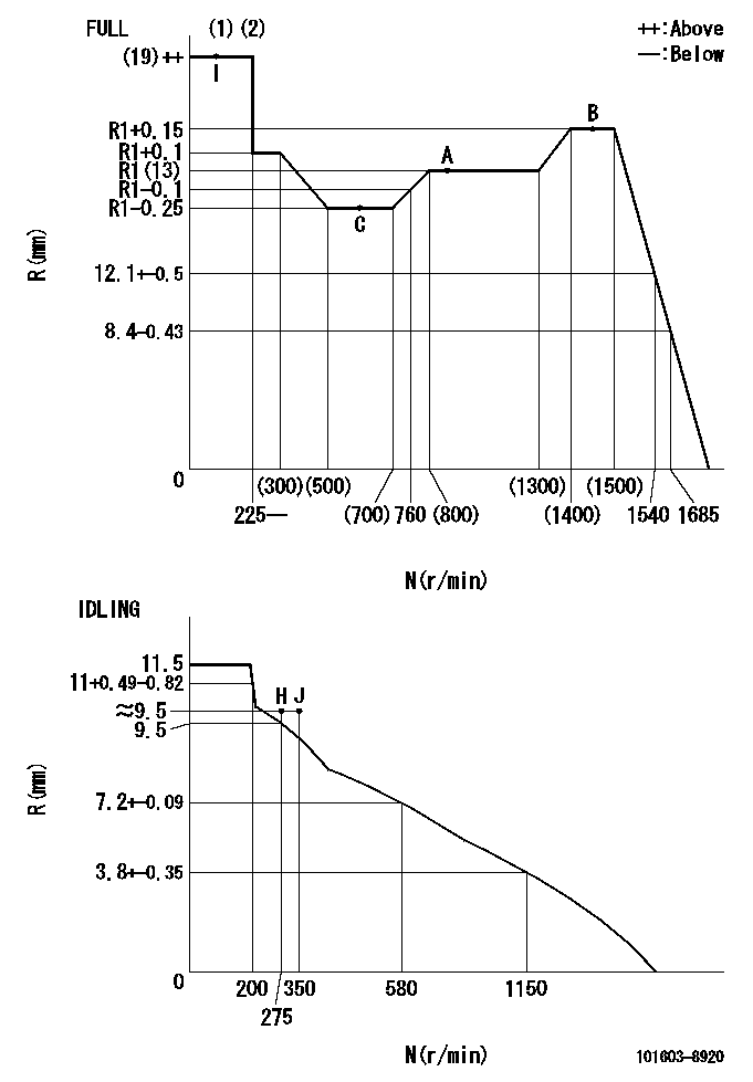
N:Pump speed
R:Rack position (mm)
(1)Torque cam stamping: T1
(2)Tolerance for racks not indicated: +-0.05mm.
----------
T1=K09
----------
----------
T1=K09
----------
Speed control lever angle

F:Full speed
I:Idle
(1)Use the pin at R = aa
(2)Stopper bolt setting
----------
aa=35mm
----------
a=10deg+-5deg b=40deg+-3deg
----------
aa=35mm
----------
a=10deg+-5deg b=40deg+-3deg
Stop lever angle

N:Pump normal
S:Stop the pump.
(1)Use the pin at R = aa
----------
aa=45mm
----------
a=12.5deg+-5deg b=40deg+-5deg
----------
aa=45mm
----------
a=12.5deg+-5deg b=40deg+-5deg
0000001501 I/P WITH LOAD PLUNGER ADJ
Plunger assembly number: PL (stamping: ST)
1. Adjustment procedures
(1)Insert the pre-stroke adjusting shims L1 for each cylinder.
(2)Adjust injection quantity.(max. var. bet. cyl. idling a1, full a2)
(3)At basic point A, adjust so that the pre-stroke is L2.
(4)Reconfirm the injection quantity.
----------
PL=131153-9020 ST=A769 L1=1mm L2=4.7+-0.05mm a1=+-14% a2=+-2.5%
----------
----------
PL=131153-9020 ST=A769 L1=1mm L2=4.7+-0.05mm a1=+-14% a2=+-2.5%
----------
Timing setting
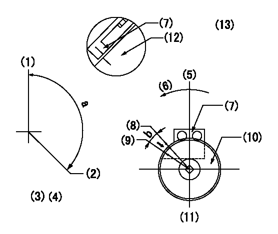
(1)Pump vertical direction
(2)Position of timer's threaded hole at No 1 cylinder's beginning of injection
(3)B.T.D.C.: aa
(4)At rack position = bb
(5)Pump vertical direction
(6)Direction of rotation
(7)Pointer
(8)Timing device stamping
(9)Pointer stamping
(10)Timing device
(11)Move b deg and stamp both at the same time as shown above.
(12)Outside circumference of timing device
(13)Secondary timing stamping position for the No. 1 cylinder's beginning of injection
----------
aa=6deg bb=R1(13)mm
----------
a=(150deg) b=1deg
----------
aa=6deg bb=R1(13)mm
----------
a=(150deg) b=1deg
Information:
TIMING PIN AND PULLER INSTALLED (Typical Example)
1. FT887 Timing Pin. (Fabricated Tool.) 2. 9S8520 Puller Group.5. Install the 1P2320 Puller and remove the camshaft small outer gear.
PULLING SMALL OUTER GEAR6. Remove the spacer immediately behind the gear.7. Install the 1P2321 Puller and remove the camshaft large inner gear.
PULLING LARGE INNER GEARInstall Camshaft Gears
1. Heat both gears to a maximum temperature of 600° F (315° C) before installing on camshaft.2. Align keyway of large inner gear with key in camshaft. Install large inner gear on camshaft with timing mark on gear aligned with timing mark on crankshaft gear.
TIMING MARKS3. Install the spacer and small outer gear on the camshaft.
Do not drive gears onto camshaft. Serious damage can result to camshaft or camshaft thrust pin.
4. Position the automatic timing advance unit on the fuel injection pump camshaft.5. Install the tachometer drive adapter shaft and tighten shaft retaining nut to 32 2 lb. ft. (4.4 0.3 mkg).6. Remove timing pin from fuel injection pump housing and install the plug.
Have questions with 101603-8920?
Group cross 101603-8920 ZEXEL
Isuzu
101603-8920
9 400 615 283
8943913360
INJECTION-PUMP ASSEMBLY
6HH1-S
6HH1-S