Information injection-pump assembly
BOSCH
9 400 611 699
9400611699
ZEXEL
101603-8752
1016038752
ISUZU
8943959212
8943959212

Rating:
Service parts 101603-8752 INJECTION-PUMP ASSEMBLY:
1.
_

6.
COUPLING PLATE
7.
COUPLING PLATE
8.
_
9.
_
11.
Nozzle and Holder
8-94395-923-2
12.
Open Pre:MPa(Kqf/cm2)
22.1{225}
15.
NOZZLE SET
Cross reference number
BOSCH
9 400 611 699
9400611699
ZEXEL
101603-8752
1016038752
ISUZU
8943959212
8943959212
Zexel num
Bosch num
Firm num
Name
101603-8752
9 400 611 699
8943959212 ISUZU
INJECTION-PUMP ASSEMBLY
6HE1-TC K 14BF INJECTION PUMP ASSY PE6AD PE
6HE1-TC K 14BF INJECTION PUMP ASSY PE6AD PE
Calibration Data:
Adjustment conditions
Test oil
1404 Test oil ISO4113 or {SAEJ967d}
1404 Test oil ISO4113 or {SAEJ967d}
Test oil temperature
degC
40
40
45
Nozzle and nozzle holder
105780-8140
Bosch type code
EF8511/9A
Nozzle
105780-0000
Bosch type code
DN12SD12T
Nozzle holder
105780-2080
Bosch type code
EF8511/9
Opening pressure
MPa
17.2
Opening pressure
kgf/cm2
175
Injection pipe
Outer diameter - inner diameter - length (mm) mm 6-2-600
Outer diameter - inner diameter - length (mm) mm 6-2-600
Overflow valve
132424-0620
Overflow valve opening pressure
kPa
157
123
191
Overflow valve opening pressure
kgf/cm2
1.6
1.25
1.95
Tester oil delivery pressure
kPa
157
157
157
Tester oil delivery pressure
kgf/cm2
1.6
1.6
1.6
Direction of rotation (viewed from drive side)
Left L
Left L
Injection timing adjustment
Direction of rotation (viewed from drive side)
Left L
Left L
Injection order
1-5-3-6-
2-4
Pre-stroke
mm
3.5
3.45
3.55
Rack position
Point A R=A
Point A R=A
Beginning of injection position
Governor side NO.1
Governor side NO.1
Difference between angles 1
Cal 1-5 deg. 60 59.5 60.5
Cal 1-5 deg. 60 59.5 60.5
Difference between angles 2
Cal 1-3 deg. 120 119.5 120.5
Cal 1-3 deg. 120 119.5 120.5
Difference between angles 3
Cal 1-6 deg. 180 179.5 180.5
Cal 1-6 deg. 180 179.5 180.5
Difference between angles 4
Cyl.1-2 deg. 240 239.5 240.5
Cyl.1-2 deg. 240 239.5 240.5
Difference between angles 5
Cal 1-4 deg. 300 299.5 300.5
Cal 1-4 deg. 300 299.5 300.5
Injection quantity adjustment
Adjusting point
-
Rack position
12.2
Pump speed
r/min
850
850
850
Average injection quantity
mm3/st.
98
96.4
99.6
Max. variation between cylinders
%
0
-2.5
2.5
Basic
*
Fixing the rack
*
Standard for adjustment of the maximum variation between cylinders
*
Injection quantity adjustment_02
Adjusting point
H
Rack position
9.3+-0.5
Pump speed
r/min
265
265
265
Average injection quantity
mm3/st.
10.5
9.2
11.8
Max. variation between cylinders
%
0
-14
14
Fixing the rack
*
Standard for adjustment of the maximum variation between cylinders
*
Injection quantity adjustment_03
Adjusting point
A
Rack position
R1(12.2)
Pump speed
r/min
850
850
850
Average injection quantity
mm3/st.
98
97
99
Basic
*
Fixing the lever
*
Boost pressure
kPa
70.6
70.6
Boost pressure
mmHg
530
530
Injection quantity adjustment_04
Adjusting point
B
Rack position
(R1-0.2)
Pump speed
r/min
1350
1350
1350
Average injection quantity
mm3/st.
101
97.8
104.2
Fixing the lever
*
Boost pressure
kPa
70.6
70.6
Boost pressure
mmHg
530
530
Injection quantity adjustment_05
Adjusting point
C
Rack position
(R1-1.85
)
Pump speed
r/min
850
850
850
Average injection quantity
mm3/st.
57.5
54.3
60.7
Fixing the lever
*
Boost pressure
kPa
0
0
0
Boost pressure
mmHg
0
0
0
Injection quantity adjustment_06
Adjusting point
I
Rack position
-
Pump speed
r/min
150
150
150
Average injection quantity
mm3/st.
105
105
137
Fixing the lever
*
Boost pressure
kPa
0
0
0
Boost pressure
mmHg
0
0
0
Boost compensator adjustment
Pump speed
r/min
1050
1050
1050
Rack position
R2-1.85
Boost pressure
kPa
9.3
8
10.6
Boost pressure
mmHg
70
60
80
Boost compensator adjustment_02
Pump speed
r/min
1050
1050
1050
Rack position
R2(R1-0.
05)
Boost pressure
kPa
57.3
57.3
57.3
Boost pressure
mmHg
430
430
430
Timer adjustment
Pump speed
r/min
1175--
Advance angle
deg.
0
0
0
Load
3/4
Remarks
Start
Start
Timer adjustment_02
Pump speed
r/min
1125
Advance angle
deg.
0.3
Load
3/4
Timer adjustment_03
Pump speed
r/min
1400
Advance angle
deg.
3.5
3
4
Load
4/4
Remarks
Finish
Finish
Test data Ex:
Governor adjustment
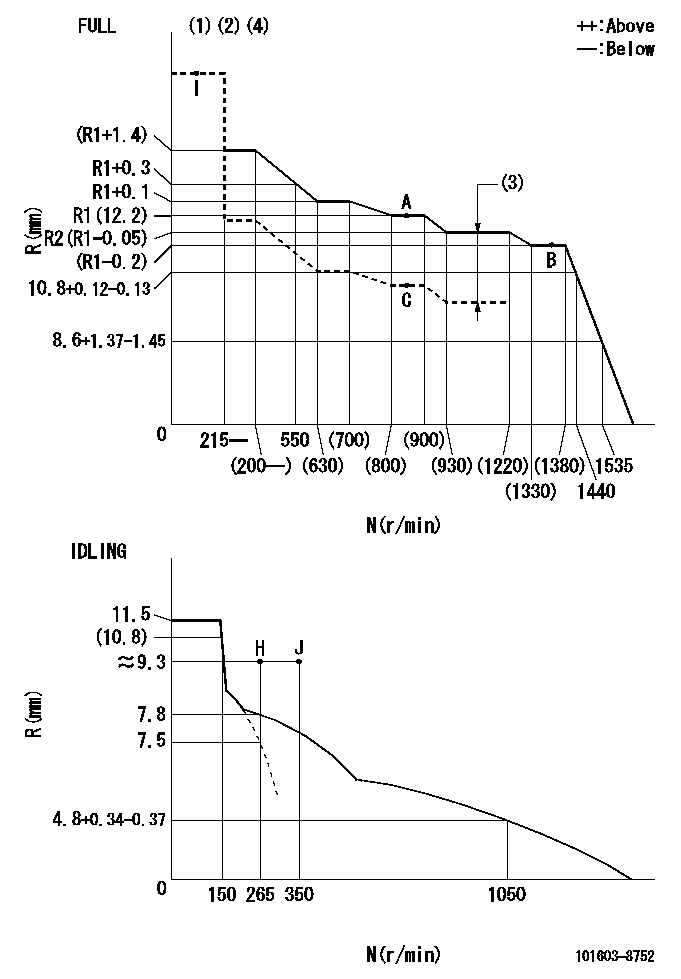
N:Pump speed
R:Rack position (mm)
(1)Torque cam stamping: T1
(2)Tolerance for racks not indicated: +-0.05mm.
(3)Boost compensator stroke: BCL
(4)Adjust so that the boost compensator pushrod protrusion R = Ra at 0 boost.
----------
T1=L05 BCL=1.85+-0.1mm Ra=12+-0.5mm
----------
----------
T1=L05 BCL=1.85+-0.1mm Ra=12+-0.5mm
----------
Speed control lever angle

F:Full speed
I:Idle
(1)Use the pin at R = aa
(2)Stopper bolt set position 'H'
----------
aa=35mm
----------
a=17deg+-5deg b=28deg+-3deg
----------
aa=35mm
----------
a=17deg+-5deg b=28deg+-3deg
Stop lever angle

N:Pump normal
S:Stop the pump.
(1)Use the pin at R = aa
----------
aa=45mm
----------
a=12.5deg+-5deg b=40deg+-5deg
----------
aa=45mm
----------
a=12.5deg+-5deg b=40deg+-5deg
Timing setting

(1)Pump vertical direction
(2)Position of timer's threaded hole at No 1 cylinder's beginning of injection
(3)B.T.D.C.: aa
(4)-
----------
aa=11deg
----------
a=(160deg)
----------
aa=11deg
----------
a=(160deg)
Information:
The problems in this chart are problems that do come about and are normally called "low power." These problems are not necessarily more common than engine problems, but they are possible problems which you need to read and check before an engine is disassembled.Read all of the items but make sure the first four are checked completely before making any engine test. Recommended Procedure1. Tachometer Error To check, connect a tachometer of known accuracy to the engine. Run the engine and make a comparison of the readings of the vehicle and test tachometers. If vehicle tachometer is bad, make repairs as necessary or install a new tachometer.2. Engine Operated at High Altitude Less oxygen at higher altitudes causes the engine horsepower to go down approximately three percent for each 1000 ft. above sea level. See the RACK SETTING INFORMATION for the correct rack setting for the higher altitude operation.3. Brakes Do Not Completely Release Check the brakes by feeling all the brake drums. If the brakes of a wheel do not completely release, the brake drum for that wheel will be hotter than the brake drums for the other wheels. With the truck lifted with a jack the wheels must have free rotation when turned by hand.4. Vehicle Operated in Too High a Gear If the operator does not shift the truck correctly or operates the truck in a "lug" condition (using the truck in too high a gear for engine rpm to go up as accelerator pedal is pushed farther down, or using the truck in a gear where engine rpm goes down with accelerator pedal at maximum travel), poor vehicle performance is the result. For best engine performance do not lug the engine more than 600 rpm below its full load speed.5. Extra Engine Driven Equipment Air compressors, hydraulic pumps, generators, and other engine driven equipment that has damage, or that was not installed correctly, or that is not in correct adjustment, can take more horsepower to drive than expected. If necessary, disconnect the equipment and test the engine.6. Speedometer Error A bad speedometer does not give the correct speed or the correct indication of fuel consumption. An indication of low speed can cause the operator to feel that he has a power problem.7. Speeds Too High The need for more horsepower is easy to see as the speed of the vehicle is increased. This is especially true if the front of the vehicle has a large surface area. Application personnel can give you the horsepower needs for a vehicle, and the horsepower necessary for different vehicle designs at different speeds.8. Overload on Vehicle See the 1100 SERIES APPLICATION SLIDE RULE (LEO-21446) for the correct load for the engine you have.9. High Moving Resistance Soft ground conditions cause a need for more horsepower. To see if the problem is the engine, test the vehicle on a surface known to be good, or test on a chassis dynamometer.10. High Wind Resistance The horsepower needs for a
Have questions with 101603-8752?
Group cross 101603-8752 ZEXEL
Isuzu
Isuzu
101603-8752
9 400 611 699
8943959212
INJECTION-PUMP ASSEMBLY
6HE1-TC
6HE1-TC