Information injection-pump assembly
BOSCH
9 400 610 672
9400610672
ZEXEL
101603-8751
1016038751
ISUZU
8943959211
8943959211

Rating:
Service parts 101603-8751 INJECTION-PUMP ASSEMBLY:
1.
_
7.
COUPLING PLATE
8.
_
9.
_
11.
Nozzle and Holder
8-94395-923-2
12.
Open Pre:MPa(Kqf/cm2)
22.1{225}
15.
NOZZLE SET
Cross reference number
BOSCH
9 400 610 672
9400610672
ZEXEL
101603-8751
1016038751
ISUZU
8943959211
8943959211
Zexel num
Bosch num
Firm num
Name
Calibration Data:
Adjustment conditions
Test oil
1404 Test oil ISO4113 or {SAEJ967d}
1404 Test oil ISO4113 or {SAEJ967d}
Test oil temperature
degC
40
40
45
Nozzle and nozzle holder
105780-8140
Bosch type code
EF8511/9A
Nozzle
105780-0000
Bosch type code
DN12SD12T
Nozzle holder
105780-2080
Bosch type code
EF8511/9
Opening pressure
MPa
17.2
Opening pressure
kgf/cm2
175
Injection pipe
Outer diameter - inner diameter - length (mm) mm 6-2-600
Outer diameter - inner diameter - length (mm) mm 6-2-600
Overflow valve
132424-0620
Overflow valve opening pressure
kPa
157
123
191
Overflow valve opening pressure
kgf/cm2
1.6
1.25
1.95
Tester oil delivery pressure
kPa
157
157
157
Tester oil delivery pressure
kgf/cm2
1.6
1.6
1.6
Direction of rotation (viewed from drive side)
Left L
Left L
Injection timing adjustment
Direction of rotation (viewed from drive side)
Left L
Left L
Injection order
1-5-3-6-
2-4
Pre-stroke
mm
3.5
3.45
3.55
Rack position
Point A R=A
Point A R=A
Beginning of injection position
Governor side NO.1
Governor side NO.1
Difference between angles 1
Cal 1-5 deg. 60 59.5 60.5
Cal 1-5 deg. 60 59.5 60.5
Difference between angles 2
Cal 1-3 deg. 120 119.5 120.5
Cal 1-3 deg. 120 119.5 120.5
Difference between angles 3
Cal 1-6 deg. 180 179.5 180.5
Cal 1-6 deg. 180 179.5 180.5
Difference between angles 4
Cyl.1-2 deg. 240 239.5 240.5
Cyl.1-2 deg. 240 239.5 240.5
Difference between angles 5
Cal 1-4 deg. 300 299.5 300.5
Cal 1-4 deg. 300 299.5 300.5
Injection quantity adjustment
Adjusting point
-
Rack position
12.4
Pump speed
r/min
850
850
850
Average injection quantity
mm3/st.
98
96.4
99.6
Max. variation between cylinders
%
0
-2.5
2.5
Basic
*
Fixing the rack
*
Standard for adjustment of the maximum variation between cylinders
*
Injection quantity adjustment_02
Adjusting point
H
Rack position
9.5+-0.5
Pump speed
r/min
265
265
265
Average injection quantity
mm3/st.
10.5
9.2
11.8
Max. variation between cylinders
%
0
-14
14
Fixing the rack
*
Standard for adjustment of the maximum variation between cylinders
*
Injection quantity adjustment_03
Adjusting point
A
Rack position
R1(12.4)
Pump speed
r/min
850
850
850
Average injection quantity
mm3/st.
98
97
99
Basic
*
Fixing the lever
*
Boost pressure
kPa
66.7
66.7
Boost pressure
mmHg
500
500
Injection quantity adjustment_04
Adjusting point
B
Rack position
R1-0.2
Pump speed
r/min
1400
1400
1400
Average injection quantity
mm3/st.
102.5
99.3
105.7
Fixing the lever
*
Boost pressure
kPa
66.7
66.7
Boost pressure
mmHg
500
500
Injection quantity adjustment_05
Adjusting point
C
Rack position
R1-1.65
Pump speed
r/min
850
850
850
Average injection quantity
mm3/st.
62.5
59.3
65.7
Fixing the lever
*
Boost pressure
kPa
0
0
0
Boost pressure
mmHg
0
0
0
Injection quantity adjustment_06
Adjusting point
I
Rack position
-
Pump speed
r/min
150
150
150
Average injection quantity
mm3/st.
105
105
137
Fixing the lever
*
Boost pressure
kPa
0
0
0
Boost pressure
mmHg
0
0
0
Boost compensator adjustment
Pump speed
r/min
850
850
850
Rack position
R1-1.65
Boost pressure
kPa
12
10.7
13.3
Boost pressure
mmHg
90
80
100
Boost compensator adjustment_02
Pump speed
r/min
850
850
850
Rack position
R1(12.4)
Boost pressure
kPa
53.3
46.6
60
Boost pressure
mmHg
400
350
450
Timer adjustment
Pump speed
r/min
1175--
Advance angle
deg.
0
0
0
Load
3/4
Remarks
Start
Start
Timer adjustment_02
Pump speed
r/min
1125
Advance angle
deg.
0.3
Load
3/4
Timer adjustment_03
Pump speed
r/min
1400
Advance angle
deg.
3.5
3
4
Load
4/4
Remarks
Finish
Finish
Test data Ex:
Governor adjustment
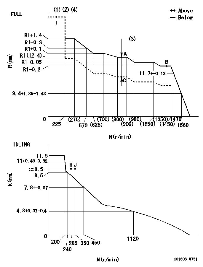
N:Pump speed
R:Rack position (mm)
(1)Torque cam stamping: T1
(2)Tolerance for racks not indicated: +-0.05mm.
(3)Boost compensator stroke: BCL
(4)Adjust so that the boost compensator pushrod protrusion R = Ra at 0 boost.
----------
T1=L05 BCL=1.65+-0.1mm Ra=12+-0.5mm
----------
----------
T1=L05 BCL=1.65+-0.1mm Ra=12+-0.5mm
----------
Speed control lever angle

F:Full speed
I:Idle
(1)Use the pin at R = aa
(2)Stopper bolt set position 'H'
----------
aa=35mm
----------
a=11deg+-5deg b=35deg+-3deg
----------
aa=35mm
----------
a=11deg+-5deg b=35deg+-3deg
Stop lever angle

N:Pump normal
S:Stop the pump.
(1)Use the pin at R = aa
----------
aa=45mm
----------
a=12.5deg+-5deg b=40deg+-5deg
----------
aa=45mm
----------
a=12.5deg+-5deg b=40deg+-5deg
Timing setting

(1)Pump vertical direction
(2)Position of timer's threaded hole at No 1 cylinder's beginning of injection
(3)B.T.D.C.: aa
(4)-
----------
aa=11deg
----------
a=(160deg)
----------
aa=11deg
----------
a=(160deg)
Information:
Recommended Procedure A. MISFIRING AND RUNNING ROUGHSee the chart, Misfiring and Running Rough. B. PROBLEM WITH VEHICLE or VEHICLE OPERATIONSee the chart, Problem With Vehicle or Vehicle Operation. C. LOW ENGINE RPM1. Governor Linkage Disconnect the governor linkage at the lever on the governor. Move the governor lever by hand until the linkage inside the governor is against the high idle stop. With the accelerator pedal all the way down, adjust the linkage so that the inside linkage is against the high idle stop. Some trucks are equipped with linkage which has spring force and some are equipped with a governor lever of the break over type. On engines with either of these, adjust the governor linkage .250 in. (6,35 mm) longer than necessary for the inside linkage to be against the high idle stop, this will keep tension on the spring at all times. For trucks with tilt cabs, do not make this check with the cab tilted.2. Governor High Idle Adjustment If the governor linkage moves the governor lever to the fully open position, check the high idle rpm with a good tachometer. If the high idle rpm is too low, turn the high idle adjustment screw counterclockwise until high idle rpm is correct. See the RACK SETTING INFORMATION for the correct high idle rpm. If high idle rpm can not be made correct with the high idle adjustment screw, there is a problem inside the governor. Disassemble the governor and check for damage to parts or the wrong parts installed in the governor. D. NOT ENOUGH AIR3. Inlet Restriction Air inlet restriction will cause low power and too much smoke when under load. Check for a restriction with a water manometer or a vacuum gauge (which measures in inches of water). Connect the gauge to the engine air inlet between the air cleaner and the engine. With gauge installed, run engine at full load rpm and check the restriction. Maximum restriction of the air inlet is 30 inches (762 mm) of water. If the indication is higher than the maximum permissible restriction, remove dirt from the filter element or install a new filter element and check the restriction again. If the indication is still too high, there must be a restriction in the inlet piping.4. Exhaust Restriction Make a visual inspection of the exhaust system and look for damage to piping or for a bad muffler. If no damage is found, you can also check the system by removing the exhaust pipes from the exhaust manifolds. With the exhaust pipes removed, start and run the engine to see if the problem is corrected. E. LOW QUALITY FUEL5. Water in Fuel Remove a small amount of fuel from the tank and check for water in the fuel. If there is water in the fuel, remove fuel from tank until it is free of water. Install a new fuel filter and fill the fuel tank with clean fuel. "Prime" (remove the air and/or low quality fuel