Information injection-pump assembly
ZEXEL
101603-8682
1016038682
ISUZU
8943959692
8943959692
Rating:
Cross reference number
ZEXEL
101603-8682
1016038682
ISUZU
8943959692
8943959692
Zexel num
Bosch num
Firm num
Name
Calibration Data:
Adjustment conditions
Test oil
1404 Test oil ISO4113 or {SAEJ967d}
1404 Test oil ISO4113 or {SAEJ967d}
Test oil temperature
degC
40
40
45
Nozzle and nozzle holder
105780-8260
Bosch type code
9 430 610 133
Nozzle
105780-0120
Bosch type code
1 688 901 990
Nozzle holder
105780-2190
Opening pressure
MPa
18
Opening pressure
kgf/cm2
184
Injection pipe
Outer diameter - inner diameter - length (mm) mm 6-2-600
Outer diameter - inner diameter - length (mm) mm 6-2-600
Overflow valve
131424-4920
Overflow valve opening pressure
kPa
127
107
147
Overflow valve opening pressure
kgf/cm2
1.3
1.1
1.5
Tester oil delivery pressure
kPa
255
255
255
Tester oil delivery pressure
kgf/cm2
2.6
2.6
2.6
Direction of rotation (viewed from drive side)
Left L
Left L
Injection timing adjustment
Direction of rotation (viewed from drive side)
Left L
Left L
Injection order
1-5-3-6-
2-4
Pre-stroke
mm
4
3.95
4.05
Beginning of injection position
Governor side NO.1
Governor side NO.1
Difference between angles 1
Cal 1-5 deg. 60 59.5 60.5
Cal 1-5 deg. 60 59.5 60.5
Difference between angles 2
Cal 1-3 deg. 120 119.5 120.5
Cal 1-3 deg. 120 119.5 120.5
Difference between angles 3
Cal 1-6 deg. 180 179.5 180.5
Cal 1-6 deg. 180 179.5 180.5
Difference between angles 4
Cyl.1-2 deg. 240 239.5 240.5
Cyl.1-2 deg. 240 239.5 240.5
Difference between angles 5
Cal 1-4 deg. 300 299.5 300.5
Cal 1-4 deg. 300 299.5 300.5
Injection quantity adjustment
Adjusting point
-
Rack position
11.6
Pump speed
r/min
850
850
850
Average injection quantity
mm3/st.
91.5
89.9
93.1
Max. variation between cylinders
%
0
-2.5
2.5
Basic
*
Fixing the rack
*
Standard for adjustment of the maximum variation between cylinders
*
Injection quantity adjustment_02
Adjusting point
Z
Rack position
9.6+-0.5
Pump speed
r/min
240
240
240
Average injection quantity
mm3/st.
9.4
8.1
10.7
Max. variation between cylinders
%
0
-14
14
Fixing the rack
*
Standard for adjustment of the maximum variation between cylinders
*
Injection quantity adjustment_03
Adjusting point
A
Rack position
R1(11.6)
Pump speed
r/min
850
850
850
Average injection quantity
mm3/st.
91.5
90.5
92.5
Basic
*
Fixing the lever
*
Injection quantity adjustment_04
Adjusting point
B
Rack position
R1+0.95
Pump speed
r/min
1425
1425
1425
Average injection quantity
mm3/st.
100.5
96.5
104.5
Fixing the lever
*
Injection quantity adjustment_05
Adjusting point
C
Rack position
R1+0.6
Pump speed
r/min
1150
1150
1150
Average injection quantity
mm3/st.
98.5
94.5
102.5
Fixing the lever
*
Injection quantity adjustment_06
Adjusting point
I
Rack position
-
Pump speed
r/min
150
150
150
Average injection quantity
mm3/st.
130
130
138
Fixing the lever
*
Rack limit
*
Timer adjustment
Pump speed
r/min
905--
Advance angle
deg.
0
0
0
Load
0/4
Remarks
Start
Start
Timer adjustment_02
Pump speed
r/min
855
Advance angle
deg.
0.3
Load
0/4
Timer adjustment_03
Pump speed
r/min
(900)
Advance angle
deg.
0
0
0
Load
4/4
Remarks
Start
Start
Timer adjustment_04
Pump speed
r/min
1425
Advance angle
deg.
5.5
5
6
Load
4/4
Remarks
Finish
Finish
Test data Ex:
Governor adjustment
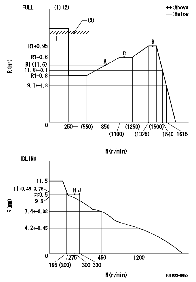
N:Pump speed
R:Rack position (mm)
(1)Torque cam stamping: T1
(2)Tolerance for racks not indicated: +-0.05mm.
(3)RACK LIMIT
----------
T1=K97
----------
----------
T1=K97
----------
Speed control lever angle
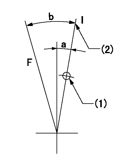
F:Full speed
I:Idle
(1)Use the hole at R = aa
(2)Stopper bolt setting
----------
aa=35mm
----------
a=13deg+-5deg b=38deg+-3deg
----------
aa=35mm
----------
a=13deg+-5deg b=38deg+-3deg
Stop lever angle
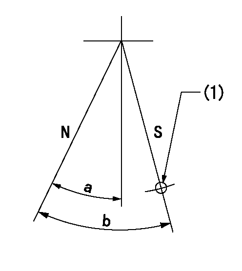
N:Pump normal
S:Stop the pump.
(1)Use the pin at R = aa
----------
aa=46.5mm
----------
a=34.5deg+-5deg b=40deg+-5deg
----------
aa=46.5mm
----------
a=34.5deg+-5deg b=40deg+-5deg
0000001501 AIR CYLINDER

1. (1) Set the speed lever to idle.
(2)Screw in air cylinder (A)
(3)Set the clearance from the speed lever (B) at approximately L.
----------
L=1mm
----------
----------
L=1mm
----------
Timing setting

(1)Pump vertical direction
(2)Position of timer's threaded hole at No 1 cylinder's beginning of injection
(3)B.T.D.C.: aa
(4)-
----------
aa=7deg
----------
a=(150deg)
----------
aa=7deg
----------
a=(150deg)
Information:
Remove Brakesaver Control Valve
1. Drain the oil from the oil pan. 2. Remove two short bolts (1) and two longer bolts (3) from manifold (2) and BrakeSaver housing. Remove manifold (2). Remove the O-ring seals from the manifold. 3. Remove oil temperature sensing unit (4) from the BrakeSaver control valve.4. Disconnect air line (5) and hose assembly (6) from the BrakeSaver control valve. 5. Remove bolt (7) and retainer (8) that hold the oil lines in the BrakeSaver control valve. 6. Disconnect oil lines (9) and (10) from the oil cooler. Remove oil lines (9) and (10) from the BrakeSaver control valve. 7. Remove bolts (12) and BrakeSaver control valve (11) from under the oil pan. The weight is 48 lb. (22 kg).8. Remove elbow (13) from the BrakeSaver control valve. Remove the O-ring seals.Install Brakesaver Control Valve
1. Inspect the O-ring seals for damage and make replacements if needed. Put clean oil on the O-ring seals. 2. Install the O-ring seals and elbow (3) on the BrakeSaver control valve.3. Make sure the O-ring seals are in position on the face of the BrakeSaver control valve. Put BrakeSaver control valve (1) in position under the oil pan. Install bolts (2) that hold the BrakeSaver control valve to the oil pan. 4. Install oil temperature sensing unit (4) in the BrakeSaver control valve.5. Connect air line (5) and hose assembly (6) to the BrakeSaver control valve. 6. Install O-ring seals (7) and (8) on manifold (9). Install manifold (9) in the BrakeSaver control valve. Install the four bolts that hold the manifold to the BrakeSaver housing. 7. Make sure the O-ring seals are in place on the oil lines and install oil lines (10) and (11). 8. Install retainer (12) to hold the oil lines in the BrakeSaver control valve. If the bottom plug in the oil pan was removed, put the split (seam) of the gasket for the plug against the oil pan. If either plug on the side of the oil pan was removed, put 5P3413 Pipe Sealant on the threads and tighten the plug to a torque of 60 8 lb. ft. (80 11 N m).9. Fill the engine with oil. See LUBRICATION AND MAINTENANCE GUIDE.Disassemble Brakesaver Control Valve
start by:a) remove BrakeSaver control valve 1. Remove O-ring seals (1) from the valve body.
Spring force is behind the cover at removal.
2. Remove four bolts (2) slowly and evenly from cover (4). Remove the cover.3. Remove cover (3) and the seal from the opposite end of the valve body. 4. Remove spool (8) as an assembly.5. Remove spring (7), stop (10), spring (6) and slug (9).6. Remove the O-ring seals and sleeve (5). 7. Remove bolt (11), plate (13) and diaphragm (12) from the spool. Make an inspection of the pin on the spool, and make a replacement of the pin if there is damage or wear.Assemble Brakesaver Control Valve
1. Install diaphragm (4) and plate (8) on valve spool (3). Make alignment of the hole in the