Information injection-pump assembly
ZEXEL
101603-8652
1016038652
ISUZU
8943959793
8943959793

Rating:
Cross reference number
ZEXEL
101603-8652
1016038652
ISUZU
8943959793
8943959793
Zexel num
Bosch num
Firm num
Name
Calibration Data:
Adjustment conditions
Test oil
1404 Test oil ISO4113 or {SAEJ967d}
1404 Test oil ISO4113 or {SAEJ967d}
Test oil temperature
degC
40
40
45
Nozzle and nozzle holder
105780-8140
Bosch type code
EF8511/9A
Nozzle
105780-0000
Bosch type code
DN12SD12T
Nozzle holder
105780-2080
Bosch type code
EF8511/9
Opening pressure
MPa
17.2
Opening pressure
kgf/cm2
175
Injection pipe
Outer diameter - inner diameter - length (mm) mm 6-2-600
Outer diameter - inner diameter - length (mm) mm 6-2-600
Overflow valve
131424-4920
Overflow valve opening pressure
kPa
127
107
147
Overflow valve opening pressure
kgf/cm2
1.3
1.1
1.5
Tester oil delivery pressure
kPa
157
157
157
Tester oil delivery pressure
kgf/cm2
1.6
1.6
1.6
Direction of rotation (viewed from drive side)
Left L
Left L
Injection timing adjustment
Direction of rotation (viewed from drive side)
Left L
Left L
Injection order
1-5-3-6-
2-4
Pre-stroke
mm
4.7
4.65
4.75
Rack position
After adjusting injection quantity. R=A
After adjusting injection quantity. R=A
Beginning of injection position
Governor side NO.1
Governor side NO.1
Difference between angles 1
Cal 1-5 deg. 60 59.5 60.5
Cal 1-5 deg. 60 59.5 60.5
Difference between angles 2
Cal 1-3 deg. 120 119.5 120.5
Cal 1-3 deg. 120 119.5 120.5
Difference between angles 3
Cal 1-6 deg. 180 179.5 180.5
Cal 1-6 deg. 180 179.5 180.5
Difference between angles 4
Cyl.1-2 deg. 240 239.5 240.5
Cyl.1-2 deg. 240 239.5 240.5
Difference between angles 5
Cal 1-4 deg. 300 299.5 300.5
Cal 1-4 deg. 300 299.5 300.5
Injection quantity adjustment
Adjusting point
-
Rack position
12.6
Pump speed
r/min
850
850
850
Average injection quantity
mm3/st.
82
80.4
83.6
Max. variation between cylinders
%
0
-2.5
2.5
Basic
*
Fixing the rack
*
Standard for adjustment of the maximum variation between cylinders
*
Injection quantity adjustment_02
Adjusting point
H
Rack position
9.5+-0.5
Pump speed
r/min
275
275
275
Average injection quantity
mm3/st.
8.5
7.2
9.8
Max. variation between cylinders
%
0
-14
14
Fixing the rack
*
Standard for adjustment of the maximum variation between cylinders
*
Injection quantity adjustment_03
Adjusting point
A
Rack position
R1(12.6)
Pump speed
r/min
850
850
850
Average injection quantity
mm3/st.
82
81
83
Basic
*
Fixing the lever
*
Injection quantity adjustment_04
Adjusting point
B
Rack position
R1(12.6)
Pump speed
r/min
1425
1425
1425
Average injection quantity
mm3/st.
88.5
85.3
91.7
Fixing the lever
*
Injection quantity adjustment_05
Adjusting point
C
Rack position
R1-0.2
Pump speed
r/min
600
600
600
Average injection quantity
mm3/st.
72.5
69.3
75.7
Fixing the lever
*
Timer adjustment
Pump speed
r/min
1300--
Advance angle
deg.
0
0
0
Remarks
Start
Start
Timer adjustment_02
Pump speed
r/min
1250
Advance angle
deg.
0.5
Timer adjustment_03
Pump speed
r/min
1400
Advance angle
deg.
4.5
4
5
Remarks
Finish
Finish
Test data Ex:
Governor adjustment
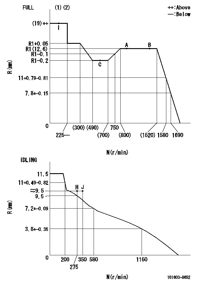
N:Pump speed
R:Rack position (mm)
(1)Torque cam stamping: T1
(2)Tolerance for racks not indicated: +-0.05mm.
----------
T1=K49
----------
----------
T1=K49
----------
Speed control lever angle
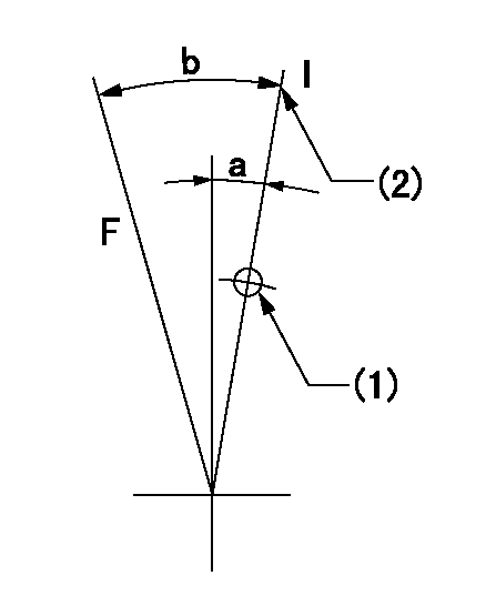
F:Full speed
I:Idle
(1)Use the hole at R = aa
(2)Stopper bolt set position 'H'
----------
aa=35mm
----------
a=14deg+-5deg b=40deg+-3deg
----------
aa=35mm
----------
a=14deg+-5deg b=40deg+-3deg
Stop lever angle
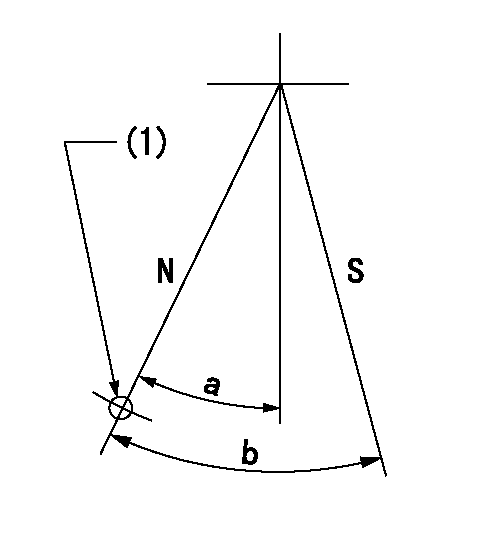
N:Pump normal
S:Stop the pump.
(1)Use the pin at R = aa
----------
aa=46.5mm
----------
a=34.5deg+-5deg b=40deg+-5deg
----------
aa=46.5mm
----------
a=34.5deg+-5deg b=40deg+-5deg
0000001501 I/P WITH LOAD PLUNGER ADJ
Plunger assembly number: PL (stamping: ST)
1. Adjustment procedures
(1)Insert the pre-stroke adjusting shims L1 for each cylinder.
(2)Adjust injection quantity.(max. var. bet. cyl. idling a1, full a2)
(3)At basic point A, adjust so that the pre-stroke is L2.
(4)Reconfirm the injection quantity.
----------
PL=131153-9020 ST=A769 L1=1mm L2=4.7+-0.05mm a1=+-14% a2=+-2.5%
----------
----------
PL=131153-9020 ST=A769 L1=1mm L2=4.7+-0.05mm a1=+-14% a2=+-2.5%
----------
Timing setting

(1)Pump vertical direction
(2)Position of timer's threaded hole at No 1 cylinder's beginning of injection
(3)B.T.D.C.: aa
(4)At rack position = bb
----------
aa=6deg bb=R1(12.6)mm
----------
a=(150deg)
----------
aa=6deg bb=R1(12.6)mm
----------
a=(150deg)
Information:
1. Remove bolt (1) from the alternator and bracket. 2. Remove the two bolts that hold bracket (3) to the timing gear cover.3. Disconnect water line (2) from the air compressor. 4. Remove bolts (4) and (5) that hold the cylinder head to the cylinder block. 5. Fasten a hoist and remove cylinder head (6). The weight is approximately 300 lb. (135 kg).
Do not put the cylinder head down on a flat surface. This can cause damage to the fuel injection valves.
6. Remove the seals from the spacer plate.Install Cylinder Head Assembly
Be sure a new gasket has been installed between the spacer plate and the cylinder block. See REMOVE AND INSTALL SPACER PLATE. 1. Thoroughly clean the spacer plate and the bottom surface of the cylinder head. Install a new head gasket and new seals (1). Later model engines have two O-ring seals on top and bottom of the spacer plate. 2. Fasten a hoist and put cylinder head (2) in position on the cylinder block. 3. Put clean engine oil on the threads of the cylinder head bolts. Install the cylinder head bolts and washers. Tighten the bolts in sequence shown in illustration A87019x1: a) Tighten bolts 1 through 20 in number sequence to a torque of 200 20 lb.ft. (270 25 N m).b) Tighten bolts 1 through 20 in number sequence to a torque of 330 15 lb.ft. (450 20 N m).c) Tighten bolts 1 through 20 in number sequence to a torque of 330 15 lb.ft. (450 20 N m) by hand.d) Install rocker shafts and push rods. See INSTALL ROCKER SHAFTS AND PUSH RODS.e) Tighten bolts 21 through 26 in number sequence to a torque of 200 20 lb.ft. (270 25 N m).f) Tighten bolts 21 through 26 in number sequence to a torque of 330 15 lb.ft. (450 20 N m).g) Tighten bolts 21 through 26 in number sequence to a torque of 330 15 lb.ft. (450 20 N m) by hand.h) Tighten the 3/8" bolts to a torque of 32 5 lb. ft. (43 7 N m). If the studs for the exhaust manifold were removed, install new studs and tighten to 20 3 lb.ft. (25 4 N m).4. Make a adjustment to the valves to have a clearance of .015 (0.38 mm) for intake and .030 (0.76 mm) for exhaust. Install the valve cover bases and the inner fuel lines. Tighten the locknuts for the valve adjustment screws to a torque of 22 3 lb.ft. (28 4 N m).5. Install the valve cover bases and the inner fuel lines. See INSTALL ROCKER SHAFT AND PUSH RODS.6. Install the valve covers. See INSTALL VALVE COVERS. 7. Connect water line (3) to the air compressor. 8. Install bolt (4) for the alternator.end by:a) install exhaust manifoldb) install fuel injection linesc) install inlet manifoldd) install water temperature regulator