Information injection-pump assembly
BOSCH
9 400 615 274
9400615274
ZEXEL
101603-8611
1016038611
ISUZU
8943959031
8943959031

Rating:
Service parts 101603-8611 INJECTION-PUMP ASSEMBLY:
1.
_

7.
COUPLING PLATE
8.
_
9.
_
11.
Nozzle and Holder
8-94395-511-1
12.
Open Pre:MPa(Kqf/cm2)
18.1{185}
15.
NOZZLE SET
Include in #1:
101603-8611
as INJECTION-PUMP ASSEMBLY
Include in #2:
104741-5482
as _
Cross reference number
BOSCH
9 400 615 274
9400615274
ZEXEL
101603-8611
1016038611
ISUZU
8943959031
8943959031
Zexel num
Bosch num
Firm num
Name
101603-8611
9 400 615 274
8943959031 ISUZU
INJECTION-PUMP ASSEMBLY
6HH1-S K 14BF INJECTION PUMP ASSY PE6AD PE
6HH1-S K 14BF INJECTION PUMP ASSY PE6AD PE
Calibration Data:
Adjustment conditions
Test oil
1404 Test oil ISO4113 or {SAEJ967d}
1404 Test oil ISO4113 or {SAEJ967d}
Test oil temperature
degC
40
40
45
Nozzle and nozzle holder
105780-8140
Bosch type code
EF8511/9A
Nozzle
105780-0000
Bosch type code
DN12SD12T
Nozzle holder
105780-2080
Bosch type code
EF8511/9
Opening pressure
MPa
17.2
Opening pressure
kgf/cm2
175
Injection pipe
Outer diameter - inner diameter - length (mm) mm 6-2-600
Outer diameter - inner diameter - length (mm) mm 6-2-600
Overflow valve
131424-4920
Overflow valve opening pressure
kPa
127
107
147
Overflow valve opening pressure
kgf/cm2
1.3
1.1
1.5
Tester oil delivery pressure
kPa
157
157
157
Tester oil delivery pressure
kgf/cm2
1.6
1.6
1.6
Direction of rotation (viewed from drive side)
Left L
Left L
Injection timing adjustment
Direction of rotation (viewed from drive side)
Left L
Left L
Injection order
1-5-3-6-
2-4
Pre-stroke
mm
4.2
4.15
4.25
Beginning of injection position
Governor side NO.1
Governor side NO.1
Difference between angles 1
Cal 1-5 deg. 60 59.5 60.5
Cal 1-5 deg. 60 59.5 60.5
Difference between angles 2
Cal 1-3 deg. 120 119.5 120.5
Cal 1-3 deg. 120 119.5 120.5
Difference between angles 3
Cal 1-6 deg. 180 179.5 180.5
Cal 1-6 deg. 180 179.5 180.5
Difference between angles 4
Cyl.1-2 deg. 240 239.5 240.5
Cyl.1-2 deg. 240 239.5 240.5
Difference between angles 5
Cal 1-4 deg. 300 299.5 300.5
Cal 1-4 deg. 300 299.5 300.5
Injection quantity adjustment
Adjusting point
-
Rack position
10.9
Pump speed
r/min
850
850
850
Average injection quantity
mm3/st.
71
69.4
72.6
Max. variation between cylinders
%
0
-2.5
2.5
Basic
*
Fixing the rack
*
Standard for adjustment of the maximum variation between cylinders
*
Injection quantity adjustment_02
Adjusting point
-
Rack position
9.6+-0.5
Pump speed
r/min
275
275
275
Average injection quantity
mm3/st.
9.4
8.1
10.7
Max. variation between cylinders
%
0
-14
14
Fixing the rack
*
Standard for adjustment of the maximum variation between cylinders
*
Remarks
Adjust only variation between cylinders; adjust governor according to governor specifications.
Adjust only variation between cylinders; adjust governor according to governor specifications.
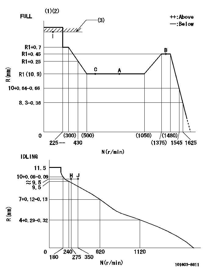
Injection quantity adjustment_03
Adjusting point
A
Rack position
R1(10.9)
Pump speed
r/min
850
850
850
Average injection quantity
mm3/st.
71
70
72
Basic
*
Fixing the lever
*
Injection quantity adjustment_04
Adjusting point
B
Rack position
R1+0.45
Pump speed
r/min
1425
1425
1425
Average injection quantity
mm3/st.
87.5
83.5
91.5
Fixing the lever
*
Injection quantity adjustment_05
Adjusting point
C
Rack position
R1
Pump speed
r/min
600
600
600
Average injection quantity
mm3/st.
57
53.8
60.2
Fixing the lever
*
Injection quantity adjustment_06
Adjusting point
I
Rack position
-
Pump speed
r/min
150
150
150
Average injection quantity
mm3/st.
125
125
133
Fixing the lever
*
Rack limit
*
Timer adjustment
Pump speed
r/min
550--
Advance angle
deg.
0
0
0
Remarks
Start
Start
Timer adjustment_02
Pump speed
r/min
500
Advance angle
deg.
0.5
Timer adjustment_03
Pump speed
r/min
1000
Advance angle
deg.
3
2.5
3.5
Remarks
Finish
Finish
Test data Ex:
Governor adjustment
N:Pump speed
R:Rack position (mm)
(1)Torque cam stamping: T1
(2)Tolerance for racks not indicated: +-0.05mm.
(3)RACK LIMIT
----------
T1=K77
----------
----------
T1=K77
----------
Speed control lever angle

F:Full speed
I:Idle
(1)Use the pin at R = aa
(2)Stopper bolt set position 'H'
----------
aa=35mm
----------
a=12deg+-5deg b=35deg+-3deg
----------
aa=35mm
----------
a=12deg+-5deg b=35deg+-3deg
Stop lever angle

N:Pump normal
S:Stop the pump.
(1)Use the pin at R = aa
----------
aa=45mm
----------
a=12.5deg+-5deg b=40deg+-5deg
----------
aa=45mm
----------
a=12.5deg+-5deg b=40deg+-5deg
Timing setting

(1)Pump vertical direction
(2)Position of timer's threaded hole at No 1 cylinder's beginning of injection
(3)B.T.D.C.: aa
(4)-
----------
aa=14deg
----------
a=(160deg)
----------
aa=14deg
----------
a=(160deg)
Information:
Do not operate or work on this product unless you have read and understood the instruction and warnings in the relevant Operation and Maintenance Manuals and relevant service literature. Failure to follow the instructions or heed the warnings could result in injury or death. Proper care is your responsibility.
New DEF sensor kits are available. The new sensor kit allows the DEF sensor to be repaired on DEF manifold assemblies.Note: If troubleshooting procedures indicate a replacement of the DEF manifold, do not replace the DEF Manifold. Repair the DEF Manifold using the DEF manifold sensor kit.Refer to Table 1 for the appropriate DEF sensor kit for the DEF manifold installed.
Table 1
DEF manifold Part Number Part Description Repair with DEF Sensor Kit
462-3219 11 inch (279mm) Manifold 593-0641
462-3610 13 inch (330mm) Manifold 593-0642
462-3232 18 inch (457mm) Manifold 593-0643
Illustration 1 g06508474New disassembly and assembly instructions are available. Refer to Disassembly and Assembly, Manifold (DEF Heater) - Disassemble and Disassembly and Assembly, Manifold (DEF Heater) - Assemble for the correct procedures.
Have questions with 101603-8611?
Group cross 101603-8611 ZEXEL
Isuzu
Isuzu
101603-8611
9 400 615 274
8943959031
INJECTION-PUMP ASSEMBLY
6HH1-S
6HH1-S