Information injection-pump assembly
BOSCH
F 019 Z10 010
f019z10010
ZEXEL
101603-8610
1016038610
Rating:
Service parts 101603-8610 INJECTION-PUMP ASSEMBLY:
1.
_

7.
COUPLING PLATE
8.
_
9.
_
11.
Nozzle and Holder
12.
Open Pre:MPa(Kqf/cm2)
18.1{185}

15.
NOZZLE SET
Include in #1:
101603-8610
as INJECTION-PUMP ASSEMBLY
Include in #2:
104741-5481
as _
Cross reference number
BOSCH
F 019 Z10 010
f019z10010
ZEXEL
101603-8610
1016038610
Zexel num
Bosch num
Firm num
Name
Calibration Data:
Adjustment conditions
Test oil
1404 Test oil ISO4113 or {SAEJ967d}
1404 Test oil ISO4113 or {SAEJ967d}
Test oil temperature
degC
40
40
45
Nozzle and nozzle holder
105780-8140
Bosch type code
EF8511/9A
Nozzle
105780-0000
Bosch type code
DN12SD12T
Nozzle holder
105780-2080
Bosch type code
EF8511/9
Opening pressure
MPa
17.2
Opening pressure
kgf/cm2
175
Injection pipe
Outer diameter - inner diameter - length (mm) mm 6-2-600
Outer diameter - inner diameter - length (mm) mm 6-2-600
Overflow valve
131424-4920
Overflow valve opening pressure
kPa
127
107
147
Overflow valve opening pressure
kgf/cm2
1.3
1.1
1.5
Tester oil delivery pressure
kPa
157
157
157
Tester oil delivery pressure
kgf/cm2
1.6
1.6
1.6
Direction of rotation (viewed from drive side)
Left L
Left L
Injection timing adjustment
Direction of rotation (viewed from drive side)
Left L
Left L
Injection order
1-5-3-6-
2-4
Pre-stroke
mm
4.2
4.15
4.25
Beginning of injection position
Governor side NO.1
Governor side NO.1
Difference between angles 1
Cal 1-5 deg. 60 59.5 60.5
Cal 1-5 deg. 60 59.5 60.5
Difference between angles 2
Cal 1-3 deg. 120 119.5 120.5
Cal 1-3 deg. 120 119.5 120.5
Difference between angles 3
Cal 1-6 deg. 180 179.5 180.5
Cal 1-6 deg. 180 179.5 180.5
Difference between angles 4
Cyl.1-2 deg. 240 239.5 240.5
Cyl.1-2 deg. 240 239.5 240.5
Difference between angles 5
Cal 1-4 deg. 300 299.5 300.5
Cal 1-4 deg. 300 299.5 300.5
Injection quantity adjustment
Adjusting point
-
Rack position
10.9
Pump speed
r/min
850
850
850
Average injection quantity
mm3/st.
65.5
63.9
67.1
Max. variation between cylinders
%
0
-2.5
2.5
Basic
*
Fixing the rack
*
Standard for adjustment of the maximum variation between cylinders
*
Injection quantity adjustment_02
Adjusting point
-
Rack position
9.6+-0.5
Pump speed
r/min
275
275
275
Average injection quantity
mm3/st.
9.4
8.1
10.7
Max. variation between cylinders
%
0
-14
14
Fixing the rack
*
Standard for adjustment of the maximum variation between cylinders
*
Remarks
Adjust only variation between cylinders; adjust governor according to governor specifications.
Adjust only variation between cylinders; adjust governor according to governor specifications.
Injection quantity adjustment_03
Adjusting point
A
Rack position
R1(10.9)
Pump speed
r/min
850
850
850
Average injection quantity
mm3/st.
65.5
64.5
66.5
Basic
*
Fixing the lever
*
Injection quantity adjustment_04
Adjusting point
B
Rack position
R1+0.45
Pump speed
r/min
1425
1425
1425
Average injection quantity
mm3/st.
85.5
81.5
89.5
Fixing the lever
*
Injection quantity adjustment_05
Adjusting point
C
Rack position
R1
Pump speed
r/min
600
600
600
Average injection quantity
mm3/st.
52.5
49.3
55.7
Fixing the lever
*
Injection quantity adjustment_06
Adjusting point
I
Rack position
-
Pump speed
r/min
150
150
150
Average injection quantity
mm3/st.
100
100
108
Fixing the lever
*
Rack limit
*
Timer adjustment
Pump speed
r/min
550--
Advance angle
deg.
0
0
0
Remarks
Start
Start
Timer adjustment_02
Pump speed
r/min
500
Advance angle
deg.
0.5
Timer adjustment_03
Pump speed
r/min
1000
Advance angle
deg.
3
2.5
3.5
Remarks
Finish
Finish
Test data Ex:
Governor adjustment
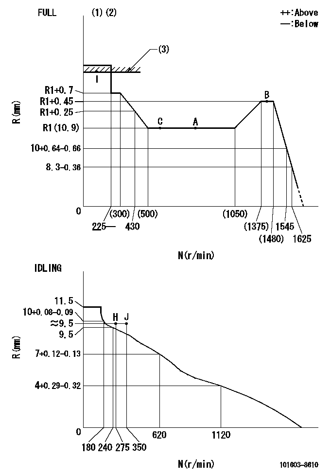
N:Pump speed
R:Rack position (mm)
(1)Torque cam stamping: T1
(2)Tolerance for racks not indicated: +-0.05mm.
(3)RACK LIMIT
----------
T1=K77
----------
----------
T1=K77
----------
Speed control lever angle

F:Full speed
I:Idle
(1)Use the pin at R = aa
(2)Stopper bolt set position 'H'
----------
aa=35mm
----------
a=12deg+-5deg b=35deg+-3deg
----------
aa=35mm
----------
a=12deg+-5deg b=35deg+-3deg
Stop lever angle

N:Pump normal
S:Stop the pump.
(1)Use the pin at R = aa
----------
aa=45mm
----------
a=12.5deg+-5deg b=40deg+-5deg
----------
aa=45mm
----------
a=12.5deg+-5deg b=40deg+-5deg
Timing setting

(1)Pump vertical direction
(2)Position of timer's threaded hole at No 1 cylinder's beginning of injection
(3)B.T.D.C.: aa
(4)-
----------
aa=14deg
----------
a=(160deg)
----------
aa=14deg
----------
a=(160deg)
Information:
2. Remove four bolts (2), nuts and cover that connect air inlet pipe (1) to the aftercooler cover.3. Put a mark on the turbocharger compressor housing in alignment with a mark on the turbocharger cartridge housing. Loosen the bolts for the turbocharger compressor housing. Carefully turn housing so air inlet pipe (1) is away from the aftercooler cover. 4. Remove bolts (3) that hold the aftercooler cover to the aftercooler base. Remove aftercooler cover (4). 5. Remove pipe (7), coupling, four bolts (5), elbow (6) and adapter (8).6. Remove the two brackets that hold the water inlet pipe to the timing gear cover. 7. Remove four bolts (9) and move elbow (10) and adapter (11) away from the aftercooler base.8. Remove the aftercooler core from the aftercooler base.Install Aftercooler Core
1. Install new O-ring seals (1) in the aftercooler core.2. Put aftercooler core (2) in position in the aftercooler base with the end that has the identification "Fresh Water" to the water inlet end of the aftercooler base. 3. Install a new O-ring seal on elbow (3). Put adapter (5) and elbow (3) in position on the aftercooler base and install four bolts (4). 4. Install new O-ring seals on elbow (7) and coupling (8).5. Install adapter (9), elbow (7), four bolts (6), coupling and pipe (10).6. Put the aftercooler cover in position on the aftercooler base and install the bolts that hold the cover to the base.7. Carefully turn the turbocharger compressor housing so the mark on the housing is in alignment with the mark on the turbocharger cartridge housing. Tighten the bolts for the compressor housing to 105 5 lb.in. (11.9 0.6 N m).
Do not cause damage to the O-ring seal between the turbocharger compressor housing and the cartridge housing.
8. Install the cover, four bolts (12) and nuts that connect air inlet pipe (11) to the aftercooler cover.9. Fill the engine with coolant.