Information injection-pump assembly
BOSCH
9 400 615 273
9400615273
ZEXEL
101603-8602
1016038602
ISUZU
8943959203
8943959203

Rating:
Include in #2:
104741-5472
as _
Cross reference number
BOSCH
9 400 615 273
9400615273
ZEXEL
101603-8602
1016038602
ISUZU
8943959203
8943959203
Zexel num
Bosch num
Firm num
Name
101603-8602
9 400 615 273
8943959203 ISUZU
INJECTION-PUMP ASSEMBLY
6HE1TC-N * K 14BF INJECTION PUMP ASSY PE6AD PE
6HE1TC-N * K 14BF INJECTION PUMP ASSY PE6AD PE
Calibration Data:
Adjustment conditions
Test oil
1404 Test oil ISO4113 or {SAEJ967d}
1404 Test oil ISO4113 or {SAEJ967d}
Test oil temperature
degC
40
40
45
Nozzle and nozzle holder
105780-8140
Bosch type code
EF8511/9A
Nozzle
105780-0000
Bosch type code
DN12SD12T
Nozzle holder
105780-2080
Bosch type code
EF8511/9
Opening pressure
MPa
17.2
Opening pressure
kgf/cm2
175
Injection pipe
Outer diameter - inner diameter - length (mm) mm 6-2-600
Outer diameter - inner diameter - length (mm) mm 6-2-600
Overflow valve
132424-0620
Overflow valve opening pressure
kPa
157
123
191
Overflow valve opening pressure
kgf/cm2
1.6
1.25
1.95
Tester oil delivery pressure
kPa
157
157
157
Tester oil delivery pressure
kgf/cm2
1.6
1.6
1.6
Direction of rotation (viewed from drive side)
Left L
Left L
Injection timing adjustment
Direction of rotation (viewed from drive side)
Left L
Left L
Injection order
1-5-3-6-
2-4
Pre-stroke
mm
3.5
3.45
3.55
Rack position
Point A R=A
Point A R=A
Beginning of injection position
Governor side NO.1
Governor side NO.1
Difference between angles 1
Cal 1-5 deg. 60 59.5 60.5
Cal 1-5 deg. 60 59.5 60.5
Difference between angles 2
Cal 1-3 deg. 120 119.5 120.5
Cal 1-3 deg. 120 119.5 120.5
Difference between angles 3
Cal 1-6 deg. 180 179.5 180.5
Cal 1-6 deg. 180 179.5 180.5
Difference between angles 4
Cyl.1-2 deg. 240 239.5 240.5
Cyl.1-2 deg. 240 239.5 240.5
Difference between angles 5
Cal 1-4 deg. 300 299.5 300.5
Cal 1-4 deg. 300 299.5 300.5
Injection quantity adjustment
Adjusting point
-
Rack position
11.5
Pump speed
r/min
850
850
850
Average injection quantity
mm3/st.
82
80.4
83.6
Max. variation between cylinders
%
0
-2.5
2.5
Basic
*
Fixing the rack
*
Standard for adjustment of the maximum variation between cylinders
*
Injection quantity adjustment_02
Adjusting point
H
Rack position
9.3+-0.5
Pump speed
r/min
265
265
265
Average injection quantity
mm3/st.
10.5
9.2
11.8
Max. variation between cylinders
%
0
-14
14
Fixing the rack
*
Standard for adjustment of the maximum variation between cylinders
*
Injection quantity adjustment_03
Adjusting point
A
Rack position
R1(11.5)
Pump speed
r/min
850
850
850
Average injection quantity
mm3/st.
82
81
83
Basic
*
Fixing the lever
*
Boost pressure
kPa
45.3
45.3
Boost pressure
mmHg
340
340
Injection quantity adjustment_04
Adjusting point
B
Rack position
(R1-0.35
)
Pump speed
r/min
1350
1350
1350
Average injection quantity
mm3/st.
86
82.8
89.2
Fixing the lever
*
Boost pressure
kPa
45.3
45.3
Boost pressure
mmHg
340
340
Injection quantity adjustment_05
Adjusting point
C
Rack position
R1-0.8
Pump speed
r/min
850
850
850
Average injection quantity
mm3/st.
68.5
65.3
71.7
Fixing the lever
*
Boost pressure
kPa
0
0
0
Boost pressure
mmHg
0
0
0
Injection quantity adjustment_06
Adjusting point
I
Rack position
-
Pump speed
r/min
150
150
150
Average injection quantity
mm3/st.
105
105
137
Fixing the lever
*
Boost pressure
kPa
0
0
0
Boost pressure
mmHg
0
0
0
Boost compensator adjustment
Pump speed
r/min
850
850
850
Rack position
R1-0.8
Boost pressure
kPa
12
10.7
13.3
Boost pressure
mmHg
90
80
100
Boost compensator adjustment_02
Pump speed
r/min
850
850
850
Rack position
R1(11.5)
Boost pressure
kPa
32
25.3
38.7
Boost pressure
mmHg
240
190
290
Timer adjustment
Pump speed
r/min
1175--
Advance angle
deg.
0
0
0
Load
3/4
Remarks
Start
Start
Timer adjustment_02
Pump speed
r/min
1125
Advance angle
deg.
0.3
Load
3/4
Timer adjustment_03
Pump speed
r/min
1400
Advance angle
deg.
3.5
3
4
Load
4/4
Remarks
Finish
Finish
Test data Ex:
Governor adjustment
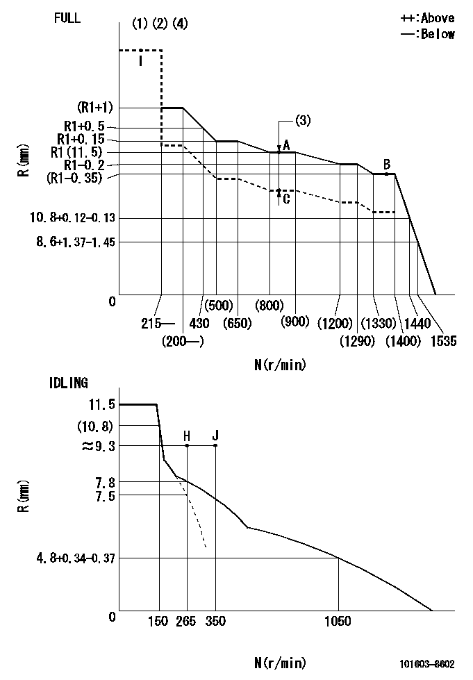
N:Pump speed
R:Rack position (mm)
(1)Torque cam stamping: T1
(2)Tolerance for racks not indicated: +-0.05mm.
(3)Boost compensator stroke: BCL
(4)Adjust so that the boost compensator pushrod protrusion R = Ra at 0 boost.
----------
T1=N46 BCL=0.8+-0.1mm Ra=12+-0.5mm
----------
----------
T1=N46 BCL=0.8+-0.1mm Ra=12+-0.5mm
----------
Speed control lever angle

F:Full speed
I:Idle
(1)Use the pin at R = aa
(2)Stopper bolt setting
----------
aa=35mm
----------
a=17deg+-5deg b=28deg+-3deg
----------
aa=35mm
----------
a=17deg+-5deg b=28deg+-3deg
Stop lever angle

N:Pump normal
S:Stop the pump.
(1)Use the pin at R = aa
----------
aa=45mm
----------
a=12.5deg+-5deg b=40deg+-5deg
----------
aa=45mm
----------
a=12.5deg+-5deg b=40deg+-5deg
Timing setting

(1)Pump vertical direction
(2)Position of timer's threaded hole at No 1 cylinder's beginning of injection
(3)B.T.D.C.: aa
(4)-
----------
aa=9deg
----------
a=(150deg)
----------
aa=9deg
----------
a=(150deg)
Information:
2. Disconnect air compressor line (2) and fuel ratio control line (3) from the aftercooler housing.3. Remove four bolts (1), nuts and cover that connect the inlet pipe to the aftercooler housing. 4. Put a mark on the turbocharger compressor housing in alignment with a mark on the turbocharger cartridge housing. Loosen the bolts for the turbocharger compressor housing. Turn the housing so air inlet pipe (4) is away from the aftercooler housing.5. Remove bolts (5) that hold the aftercooler housing to the cylinder head.6. Fasten a hoist to the aftercooler housing and remove the aftercooler housing from the engine. Weight is 95 lb. (43 kg).Install Aftercooler Housing
1. Install new O-ring seals on the aftercooler water inlet and outlet pipes. 2. Fasten a hoist to aftercooler housing (1) and put the aftercooler housing in position on the water pipes and cylinder head.3. Put 9S3263 Thread Lock on the threads of the bolts and install the bolts that hold the aftercooler housing to the cylinder head. 4. Turn the turbocharger compressor housing carefully so the mark on the housing is in alignment with the mark on the turbocharger cartridge housing. Tighten bolts (2) for the compressor housing to 105 5 lb.in. (11.9 0.6 N m).
Do not cause damage to the O-ring seal between the turbocharger compressor housing and the cartridge housing.
5. Install the four bolts and nuts that connect the air inlet pipe to the aftercooler housing.6. Connect the air compressor line and fuel ratio control line.7. Fill engine with coolant.end by:a) install fuel filter base
Have questions with 101603-8602?
Group cross 101603-8602 ZEXEL
Isuzu
101603-8602
9 400 615 273
8943959203
INJECTION-PUMP ASSEMBLY
6HE1TC-N
6HE1TC-N