Information injection-pump assembly
ZEXEL
101603-8591
1016038591
ISUZU
8943959191
8943959191
Rating:
Cross reference number
ZEXEL
101603-8591
1016038591
ISUZU
8943959191
8943959191
Zexel num
Bosch num
Firm num
Name
Calibration Data:
Adjustment conditions
Test oil
1404 Test oil ISO4113 or {SAEJ967d}
1404 Test oil ISO4113 or {SAEJ967d}
Test oil temperature
degC
40
40
45
Nozzle and nozzle holder
105780-8140
Bosch type code
EF8511/9A
Nozzle
105780-0000
Bosch type code
DN12SD12T
Nozzle holder
105780-2080
Bosch type code
EF8511/9
Opening pressure
MPa
17.2
Opening pressure
kgf/cm2
175
Injection pipe
Outer diameter - inner diameter - length (mm) mm 6-2-600
Outer diameter - inner diameter - length (mm) mm 6-2-600
Overflow valve
132424-0620
Overflow valve opening pressure
kPa
157
123
191
Overflow valve opening pressure
kgf/cm2
1.6
1.25
1.95
Tester oil delivery pressure
kPa
157
157
157
Tester oil delivery pressure
kgf/cm2
1.6
1.6
1.6
Direction of rotation (viewed from drive side)
Left L
Left L
Injection timing adjustment
Direction of rotation (viewed from drive side)
Left L
Left L
Injection order
1-5-3-6-
2-4
Pre-stroke
mm
3.5
3.45
3.55
Rack position
Point A R=A
Point A R=A
Beginning of injection position
Governor side NO.1
Governor side NO.1
Difference between angles 1
Cal 1-5 deg. 60 59.5 60.5
Cal 1-5 deg. 60 59.5 60.5
Difference between angles 2
Cal 1-3 deg. 120 119.5 120.5
Cal 1-3 deg. 120 119.5 120.5
Difference between angles 3
Cal 1-6 deg. 180 179.5 180.5
Cal 1-6 deg. 180 179.5 180.5
Difference between angles 4
Cyl.1-2 deg. 240 239.5 240.5
Cyl.1-2 deg. 240 239.5 240.5
Difference between angles 5
Cal 1-4 deg. 300 299.5 300.5
Cal 1-4 deg. 300 299.5 300.5
Injection quantity adjustment
Adjusting point
-
Rack position
12.4
Pump speed
r/min
850
850
850
Average injection quantity
mm3/st.
98
96.4
99.6
Max. variation between cylinders
%
0
-2.5
2.5
Basic
*
Fixing the rack
*
Standard for adjustment of the maximum variation between cylinders
*
Injection quantity adjustment_02
Adjusting point
H
Rack position
9.5+-0.5
Pump speed
r/min
265
265
265
Average injection quantity
mm3/st.
10.5
9.2
11.8
Max. variation between cylinders
%
0
-14
14
Fixing the rack
*
Standard for adjustment of the maximum variation between cylinders
*
Injection quantity adjustment_03
Adjusting point
A
Rack position
R1(12.4)
Pump speed
r/min
850
850
850
Average injection quantity
mm3/st.
98
97
99
Basic
*
Fixing the lever
*
Boost pressure
kPa
48
48
Boost pressure
mmHg
360
360
Injection quantity adjustment_04
Adjusting point
B
Rack position
R1-0.2
Pump speed
r/min
1400
1400
1400
Average injection quantity
mm3/st.
102.5
99.3
105.7
Fixing the lever
*
Boost pressure
kPa
48
48
Boost pressure
mmHg
360
360
Injection quantity adjustment_05
Adjusting point
C
Rack position
R1-1.55
Pump speed
r/min
850
850
850
Average injection quantity
mm3/st.
65
61.8
68.2
Fixing the lever
*
Boost pressure
kPa
0
0
0
Boost pressure
mmHg
0
0
0
Injection quantity adjustment_06
Adjusting point
I
Rack position
-
Pump speed
r/min
150
150
150
Average injection quantity
mm3/st.
105
105
137
Fixing the lever
*
Boost pressure
kPa
0
0
0
Boost pressure
mmHg
0
0
0
Boost compensator adjustment
Pump speed
r/min
850
850
850
Rack position
R1-1.55
Boost pressure
kPa
12
10.7
13.3
Boost pressure
mmHg
90
80
100
Boost compensator adjustment_02
Pump speed
r/min
850
850
850
Rack position
R1(12.4)
Boost pressure
kPa
34.7
28
41.4
Boost pressure
mmHg
260
210
310
Timer adjustment
Pump speed
r/min
1175--
Advance angle
deg.
0
0
0
Load
3/4
Remarks
Start
Start
Timer adjustment_02
Pump speed
r/min
1125
Advance angle
deg.
0.3
Load
3/4
Timer adjustment_03
Pump speed
r/min
1400
Advance angle
deg.
3.5
3
4
Load
4/4
Remarks
Finish
Finish
Test data Ex:
Governor adjustment
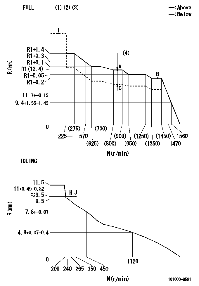
N:Pump speed
R:Rack position (mm)
(1)Torque cam stamping: T1
(2)Tolerance for racks not indicated: +-0.05mm.
(3)Adjust so that the boost compensator pushrod protrusion R = Ra at 0 boost.
(4)Boost compensator stroke: BCL
----------
T1=L05 Ra=12+-0.5mm BCL=1.55+-0.1mm
----------
----------
T1=L05 Ra=12+-0.5mm BCL=1.55+-0.1mm
----------
Speed control lever angle

F:Full speed
I:Idle
(1)Use the pin at R = aa
(2)Stopper bolt set position 'H'
----------
aa=35mm
----------
a=11deg+-5deg b=35deg+-3deg
----------
aa=35mm
----------
a=11deg+-5deg b=35deg+-3deg
Stop lever angle

N:Pump normal
S:Stop the pump.
(1)Use the pin at R = aa
----------
aa=45mm
----------
a=12.5deg+-5deg b=40deg+-5deg
----------
aa=45mm
----------
a=12.5deg+-5deg b=40deg+-5deg
Timing setting

(1)Pump vertical direction
(2)Position of timer's threaded hole at No 1 cylinder's beginning of injection
(3)B.T.D.C.: aa
(4)-
----------
aa=9deg
----------
a=(150deg)
----------
aa=9deg
----------
a=(150deg)
Information:
Remove Fuel Ratio Control
1. Disconnect line (1) from the fuel ratio control.2. Remove the wire seal from the bolts.3. Remove two bolts (2). Remove fuel ratio control (3) after it is moved down and out from the collar.Install Fuel Ratio Control
1. Put the fuel ratio control on the governor. 2. Be sure bolt (2) of the fuel ratio control is connected in the groove of collar (1).3. Install the two bolts that hold the fuel ratio control on the governor.4. Connect the line to the fuel ratio control.5. Install a wire seal on the bolts.Disassemble Fuel Ratio Control
start by:a) remove fuel ratio control 1. Remove the bolts and the housing (1).2. Remove wire seal (2) from the bolts. 3. Remove valve assembly (3).4. Remove seal (4) and O-ring seal from valve.5. Remove the retainer (5) and two springs (6). 6. Remove three bolts (9) and cover (10).7. Remove valve (7), diaphragm (8), retainer and spring. 8. Remove pin (12) from valve (7).9. Remove cover (11) from the valve.10. Remove the seal from the cover (11).Assemble Fuel Ratio Control
1. Put clean engine oil on lip of seal. Install the seal (1) in cover (2). Install seal so lip of seal is toward the inside of the cover. 2. Install the valve (3) into cover (2).3. Install the pin that holds cover on valve. 4. Install spring (7) and the retainer (6) in cover (8).5. Install diaphragm (5) on the valve assembly (4) and in the cover. 6. Install cover and three bolts (11) that hold covers together. Install wire seal on the bolts with tool group (A) after the fuel ratio control is installed and adjustments are made to it.7. Put clean engine oil on seal and ring seal. Install the seals (1) on valve.8. Install the two springs (13), retainer, and valve assembly (12).9. Install housing (9) and two bolts.end by: a) install fuel ratio control