Information injection-pump assembly
BOSCH
9 400 610 664
9400610664
ZEXEL
101603-8581
1016038581
ISUZU
8943959052
8943959052
Rating:
Service parts 101603-8581 INJECTION-PUMP ASSEMBLY:
1.
_

7.
COUPLING PLATE
8.
_
9.
_
11.
Nozzle and Holder
8-94390-499-0
12.
Open Pre:MPa(Kqf/cm2)
18.1{185}
15.
NOZZLE SET
Include in #1:
101603-8581
as INJECTION-PUMP ASSEMBLY
Include in #2:
104749-5220
as _
Cross reference number
BOSCH
9 400 610 664
9400610664
ZEXEL
101603-8581
1016038581
ISUZU
8943959052
8943959052
Zexel num
Bosch num
Firm num
Name
101603-8581
9 400 610 664
8943959052 ISUZU
INJECTION-PUMP ASSEMBLY
6HH1-N K
6HH1-N K
Calibration Data:
Adjustment conditions
Test oil
1404 Test oil ISO4113 or {SAEJ967d}
1404 Test oil ISO4113 or {SAEJ967d}
Test oil temperature
degC
40
40
45
Nozzle and nozzle holder
105780-8140
Bosch type code
EF8511/9A
Nozzle
105780-0000
Bosch type code
DN12SD12T
Nozzle holder
105780-2080
Bosch type code
EF8511/9
Opening pressure
MPa
17.2
Opening pressure
kgf/cm2
175
Injection pipe
Outer diameter - inner diameter - length (mm) mm 6-2-600
Outer diameter - inner diameter - length (mm) mm 6-2-600
Overflow valve
131424-4920
Overflow valve opening pressure
kPa
127
107
147
Overflow valve opening pressure
kgf/cm2
1.3
1.1
1.5
Tester oil delivery pressure
kPa
157
157
157
Tester oil delivery pressure
kgf/cm2
1.6
1.6
1.6
Direction of rotation (viewed from drive side)
Left L
Left L
Injection timing adjustment
Direction of rotation (viewed from drive side)
Left L
Left L
Injection order
1-5-3-6-
2-4
Pre-stroke
mm
4.7
4.65
4.75
Rack position
After adjusting injection quantity. R=A
After adjusting injection quantity. R=A
Beginning of injection position
Governor side NO.1
Governor side NO.1
Difference between angles 1
Cal 1-5 deg. 60 59.5 60.5
Cal 1-5 deg. 60 59.5 60.5
Difference between angles 2
Cal 1-3 deg. 120 119.5 120.5
Cal 1-3 deg. 120 119.5 120.5
Difference between angles 3
Cal 1-6 deg. 180 179.5 180.5
Cal 1-6 deg. 180 179.5 180.5
Difference between angles 4
Cyl.1-2 deg. 240 239.5 240.5
Cyl.1-2 deg. 240 239.5 240.5
Difference between angles 5
Cal 1-4 deg. 300 299.5 300.5
Cal 1-4 deg. 300 299.5 300.5
Injection quantity adjustment
Adjusting point
-
Rack position
12.1
Pump speed
r/min
850
850
850
Average injection quantity
mm3/st.
72.5
70.9
74.1
Max. variation between cylinders
%
0
-2.5
2.5
Basic
*
Fixing the rack
*
Standard for adjustment of the maximum variation between cylinders
*
Injection quantity adjustment_02
Adjusting point
H
Rack position
9.5+-0.5
Pump speed
r/min
275
275
275
Average injection quantity
mm3/st.
8.5
7.2
9.8
Max. variation between cylinders
%
0
-14
14
Fixing the rack
*
Standard for adjustment of the maximum variation between cylinders
*
Injection quantity adjustment_03
Adjusting point
A
Rack position
R1(12.1)
Pump speed
r/min
850
850
850
Average injection quantity
mm3/st.
72.5
71.5
73.5
Basic
*
Fixing the lever
*
Injection quantity adjustment_04
Adjusting point
B
Rack position
R1(12.1)
Pump speed
r/min
1400
1400
1400
Average injection quantity
mm3/st.
74.5
70.5
78.5
Fixing the lever
*
Timer adjustment
Pump speed
r/min
-
Advance angle
deg.
0
0
0
Remarks
Measure speed (beginning of operation).
Measure speed (beginning of operation).
Timer adjustment_02
Pump speed
r/min
-
Advance angle
deg.
4.5
4.5
4.5
Remarks
Measure the actual speed, stop
Measure the actual speed, stop
Test data Ex:
Governor adjustment
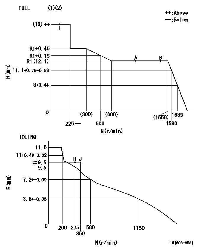
N:Pump speed
R:Rack position (mm)
(1)Torque cam stamping: T1
(2)Tolerance for racks not indicated: +-0.05mm.
----------
T1=L58
----------
----------
T1=L58
----------
Speed control lever angle

F:Full speed
I:Idle
(1)Use the hole at R = aa
(2)Stopper bolt set position 'H'
----------
aa=35mm
----------
a=10deg+-5deg b=40deg+-3deg
----------
aa=35mm
----------
a=10deg+-5deg b=40deg+-3deg
Stop lever angle

N:Pump normal
S:Stop the pump.
(1)Use the pin at R = aa
----------
aa=45mm
----------
a=12.5deg+-5deg b=40deg+-5deg
----------
aa=45mm
----------
a=12.5deg+-5deg b=40deg+-5deg
0000001501 I/P WITH LOAD PLUNGER ADJ
Plunger assembly number: PL (stamping: ST)
1. Adjustment procedures
(1)Insert the pre-stroke adjusting shims L1 for each cylinder.
(2)Adjust injection quantity.(max. var. bet. cyl. idling a1, full a2)
(3)At basic point A, adjust so that the pre-stroke is L2.
(4)Reconfirm the injection quantity.
----------
PL=131153-9020 ST=A769 L1=1mm L2=4.7+-0.05mm a1=+-14% a2=+-2.5%
----------
----------
PL=131153-9020 ST=A769 L1=1mm L2=4.7+-0.05mm a1=+-14% a2=+-2.5%
----------
Timing setting

(1)Pump vertical direction
(2)Position of timer's threaded hole at No 1 cylinder's beginning of injection
(3)B.T.D.C.: aa
(4)At rack position = bb
----------
aa=6deg bb=R1(12.1)mm
----------
a=(150deg)
----------
aa=6deg bb=R1(12.1)mm
----------
a=(150deg)
Information:
start by:a) remove fuel transfer pump 1. Remove bolts (1). Remove cover (2) from the fuel transfer pump. 2. Remove bolt (3). Remove gasket, spring and plunger from under bolt.3. Remove gear (4).4. Remove shaft assembly (5). 5. Remove O-ring seal (7) from body assembly.6. Install a 5/16"-18 NC forged eyebolt (6) in the plug. Remove plug (8) and O-ring seal. Remove the O-ring seal from the plug. 7. Remove valve assembly (9). 8. Remove two lip seals (10) from the body assembly. 9. Remove two bearings (11) from the body assembly with tooling (A).Assemble Fuel Transfer Pump (Later)
1. Install bearings in body (1) with tooling (A). Install bearing on gear end of body to a depth of .03 .02 in. (0.76 0.51 mm) below the surface of the body. Install the bearing on the opposite end of the body even with the body surface. 2. Put 4H5363 Sealant on the outside diameters of the seals. Install the lip seals in the body assembly with tooling (A). Install the first seal with lip toward bearing. Install the lip seal to a depth of .406 .010 (10.31 0.25 mm). Install the second seal with lip away from bearing. Make sure the second lip seal is even with the surface of the body assembly. 3. Install the valve assembly in the body assembly with tooling (A) to a depth of .57 .02 in. (14.5 0.5 mm). 4. Install O-ring seal (3) on the plug. Install a 5/16"-18 NC forged eyebolt (2) in the plug. Put a small amount of clean diesel fuel on the O-ring seal and install plug (4) in the body assembly. Make sure plug is even with the surface of the body.5. Install O-ring seal on the body assembly. 6. Put a small amount of clean diesel fuel on the lip seals. Put tool (B) in position on shaft assembly. Install shaft assembly (5) in the body assembly. 7. Install gear (7).
Do not get liquid gasket material into pump.
8. Put 7M7260 Liquid Gasket Material on the body assembly surface that makes contact with the cover. Install cover (6).9. Shaft assembly must turn by hand after cover is installed. 10. Install plunger (8), spring (9), gasket (11) and plug (10) in body assembly. Tighten plug to a torque of 27 3 lb. ft. (38 4 N m).end by:a) install fuel transfer pump
Have questions with 101603-8581?
Group cross 101603-8581 ZEXEL
Isuzu
Isuzu
101603-8581
9 400 610 664
8943959052
INJECTION-PUMP ASSEMBLY
6HH1-N
6HH1-N