Information injection-pump assembly
ZEXEL
101603-8580
1016038580
ISUZU
8943959051
8943959051
Rating:
Service parts 101603-8580 INJECTION-PUMP ASSEMBLY:
1.
_

7.
COUPLING PLATE
8.
_
9.
_
11.
Nozzle and Holder
8-94395-511-1
12.
Open Pre:MPa(Kqf/cm2)
18.1{185}

15.
NOZZLE SET
Cross reference number
ZEXEL
101603-8580
1016038580
ISUZU
8943959051
8943959051
Zexel num
Bosch num
Firm num
Name
Calibration Data:
Adjustment conditions
Test oil
1404 Test oil ISO4113 or {SAEJ967d}
1404 Test oil ISO4113 or {SAEJ967d}
Test oil temperature
degC
40
40
45
Nozzle and nozzle holder
105780-8140
Bosch type code
EF8511/9A
Nozzle
105780-0000
Bosch type code
DN12SD12T
Nozzle holder
105780-2080
Bosch type code
EF8511/9
Opening pressure
MPa
17.2
Opening pressure
kgf/cm2
175
Injection pipe
Outer diameter - inner diameter - length (mm) mm 6-2-600
Outer diameter - inner diameter - length (mm) mm 6-2-600
Overflow valve
131424-4920
Overflow valve opening pressure
kPa
127
107
147
Overflow valve opening pressure
kgf/cm2
1.3
1.1
1.5
Tester oil delivery pressure
kPa
157
157
157
Tester oil delivery pressure
kgf/cm2
1.6
1.6
1.6
Direction of rotation (viewed from drive side)
Left L
Left L
Injection timing adjustment
Direction of rotation (viewed from drive side)
Left L
Left L
Injection order
1-5-3-6-
2-4
Pre-stroke
mm
4.7
4.65
4.75
Rack position
After adjusting injection quantity. R=A
After adjusting injection quantity. R=A
Beginning of injection position
Governor side NO.1
Governor side NO.1
Difference between angles 1
Cal 1-5 deg. 60 59.5 60.5
Cal 1-5 deg. 60 59.5 60.5
Difference between angles 2
Cal 1-3 deg. 120 119.5 120.5
Cal 1-3 deg. 120 119.5 120.5
Difference between angles 3
Cal 1-6 deg. 180 179.5 180.5
Cal 1-6 deg. 180 179.5 180.5
Difference between angles 4
Cyl.1-2 deg. 240 239.5 240.5
Cyl.1-2 deg. 240 239.5 240.5
Difference between angles 5
Cal 1-4 deg. 300 299.5 300.5
Cal 1-4 deg. 300 299.5 300.5
Injection quantity adjustment
Adjusting point
-
Rack position
12
Pump speed
r/min
850
850
850
Average injection quantity
mm3/st.
69
67.4
70.6
Max. variation between cylinders
%
0
-2.5
2.5
Basic
*
Fixing the rack
*
Standard for adjustment of the maximum variation between cylinders
*
Injection quantity adjustment_02
Adjusting point
H
Rack position
9.5+-0.5
Pump speed
r/min
275
275
275
Average injection quantity
mm3/st.
8
6.7
9.3
Max. variation between cylinders
%
0
-14
14
Fixing the rack
*
Standard for adjustment of the maximum variation between cylinders
*
Injection quantity adjustment_03
Adjusting point
A
Rack position
R1(12)
Pump speed
r/min
850
850
850
Average injection quantity
mm3/st.
69
68
70
Basic
*
Fixing the lever
*
Injection quantity adjustment_04
Adjusting point
B
Rack position
R1(12)
Pump speed
r/min
1400
1400
1400
Average injection quantity
mm3/st.
76
72
80
Fixing the lever
*
Timer adjustment
Pump speed
r/min
1200
Remarks
Measure the actual advance angle.
Measure the actual advance angle.
Timer adjustment_02
Pump speed
r/min
-
Advance angle
deg.
5.5
5
6
Remarks
Measure the actual speed, stop
Measure the actual speed, stop
Test data Ex:
Governor adjustment
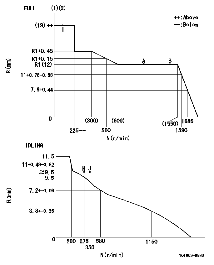
N:Pump speed
R:Rack position (mm)
(1)Torque cam stamping: T1
(2)Tolerance for racks not indicated: +-0.05mm.
----------
T1=K44
----------
----------
T1=K44
----------
Speed control lever angle

F:Full speed
I:Idle
(1)Use the hole at R = aa
(2)Stopper bolt set position 'H'
----------
aa=35mm
----------
a=10deg+-5deg b=40deg+-3deg
----------
aa=35mm
----------
a=10deg+-5deg b=40deg+-3deg
Stop lever angle

N:Pump normal
S:Stop the pump.
(1)Use the pin at R = aa
----------
aa=45mm
----------
a=12.5deg+-5deg b=40deg+-5deg
----------
aa=45mm
----------
a=12.5deg+-5deg b=40deg+-5deg
0000001501 I/P WITH LOAD PLUNGER ADJ
Plunger assembly number: PL (stamping: ST)
1. Adjustment procedures
(1)Insert the pre-stroke adjusting shims L1 for each cylinder.
(2)Adjust injection quantity.(max. var. bet. cyl. idling a1, full a2)
(3)At basic point A, adjust so that the pre-stroke is L2.
(4)Reconfirm the injection quantity.
----------
PL=131153-9020 ST=A769 L1=1mm L2=4.7+-0.05mm a1=+-14% a2=+-2.5%
----------
----------
PL=131153-9020 ST=A769 L1=1mm L2=4.7+-0.05mm a1=+-14% a2=+-2.5%
----------
Timing setting

(1)Pump vertical direction
(2)Position of timer's threaded hole at No 1 cylinder's beginning of injection
(3)B.T.D.C.: aa
(4)At rack position = bb
----------
aa=6deg bb=R1(12)mm
----------
a=(150deg)
----------
aa=6deg bb=R1(12)mm
----------
a=(150deg)
Information:
LATER
EARLIERRemove Fuel Transfer Pump
1. Disconnect fuel lines (1) and (2) from the fuel transfer pump. Put plugs and caps in the openings. 2. Remove two bolts (3) that hold the fuel transfer pump to the fuel injection pump drive.3. Remove fuel transfer pump (4).Install Fuel Transfer Pump
1. Put fuel transfer pump (1) in position so the shaft is in alignment with the groove in the fuel injection pump drive. Install the bolts that hold it. 2. Remove the plugs or caps from the openings. Connect fuel lines (2) and (3) to the fuel transfer pump.3. Remove the air from the fuel system. See PRIMING THE FUEL SYSTEM in LUBRICATION AND MAINTENANCE GUIDE.Disassemble Fuel Transfer Pump (Earlier)
start by: a) remove fuel transfer pump 1. Remove six bolts (1) that hold the transfer pump cover to transfer pump body. Remove the cover.2. Remove the plug (2), seat, spring and fuel bypass valve from cover. 3. Remove the gear (5) and shaft assembly (4) from the body (3). 4. Remove the seals (6) from the body. 5. Use tooling (A) to remove the bearing from the body.Assemble Fuel Transfer Pump (Earlier)
1. Use tooling (A) to install bearing into body.2. Use tool (B) to install inner seal in body. Install seal with lip of seal in the direction of the gears. 3. Use tool (C) to install outer seal in the body. Install seal with lip of seal toward the outside. 4. Install tool (D) on to shaft assembly (1) and install shaft assembly into body.
Tool (D) must be used to install shaft assembly. The shaft will cause damage to seals if it is not used.
5. Install idler gear (2) in the body. 6. Install fuel bypass valve (3), spring (4), seat (5), and plug into cover.7. Put a thin amount of 8S6747 Aviation Type Permatex on face of body.
Do not let Permatex get into the pump body.
8. Put the cover (6) in position on the body and install the six bolts. After tightening cover to body, the gear and shaft assembly must turn freely.end by: a) install fuel transfer pump