Information injection-pump assembly
BOSCH
9 400 610 663
9400610663
ZEXEL
101603-8571
1016038571
ISUZU
8943959041
8943959041
Rating:
Service parts 101603-8571 INJECTION-PUMP ASSEMBLY:
1.
_

7.
COUPLING PLATE
8.
_
9.
_
11.
Nozzle and Holder
8-94390-499-0
12.
Open Pre:MPa(Kqf/cm2)
18.1{185}
15.
NOZZLE SET
Cross reference number
BOSCH
9 400 610 663
9400610663
ZEXEL
101603-8571
1016038571
ISUZU
8943959041
8943959041
Zexel num
Bosch num
Firm num
Name
101603-8571
9 400 610 663
8943959041 ISUZU
INJECTION-PUMP ASSEMBLY
6HH1-S K 14BF INJECTION PUMP ASSY PE6AD PE
6HH1-S K 14BF INJECTION PUMP ASSY PE6AD PE
Calibration Data:
Adjustment conditions
Test oil
1404 Test oil ISO4113 or {SAEJ967d}
1404 Test oil ISO4113 or {SAEJ967d}
Test oil temperature
degC
40
40
45
Nozzle and nozzle holder
105780-8140
Bosch type code
EF8511/9A
Nozzle
105780-0000
Bosch type code
DN12SD12T
Nozzle holder
105780-2080
Bosch type code
EF8511/9
Opening pressure
MPa
17.2
Opening pressure
kgf/cm2
175
Injection pipe
Outer diameter - inner diameter - length (mm) mm 6-2-600
Outer diameter - inner diameter - length (mm) mm 6-2-600
Overflow valve
131424-4920
Overflow valve opening pressure
kPa
127
107
147
Overflow valve opening pressure
kgf/cm2
1.3
1.1
1.5
Tester oil delivery pressure
kPa
157
157
157
Tester oil delivery pressure
kgf/cm2
1.6
1.6
1.6
Direction of rotation (viewed from drive side)
Left L
Left L
Injection timing adjustment
Direction of rotation (viewed from drive side)
Left L
Left L
Injection order
1-5-3-6-
2-4
Pre-stroke
mm
4.7
4.65
4.75
Rack position
After adjusting injection quantity. R=A
After adjusting injection quantity. R=A
Beginning of injection position
Governor side NO.1
Governor side NO.1
Difference between angles 1
Cal 1-5 deg. 60 59.5 60.5
Cal 1-5 deg. 60 59.5 60.5
Difference between angles 2
Cal 1-3 deg. 120 119.5 120.5
Cal 1-3 deg. 120 119.5 120.5
Difference between angles 3
Cal 1-6 deg. 180 179.5 180.5
Cal 1-6 deg. 180 179.5 180.5
Difference between angles 4
Cyl.1-2 deg. 240 239.5 240.5
Cyl.1-2 deg. 240 239.5 240.5
Difference between angles 5
Cal 1-4 deg. 300 299.5 300.5
Cal 1-4 deg. 300 299.5 300.5
Injection quantity adjustment
Adjusting point
-
Rack position
12.6
Pump speed
r/min
850
850
850
Average injection quantity
mm3/st.
82
80.4
83.6
Max. variation between cylinders
%
0
-2.5
2.5
Basic
*
Fixing the rack
*
Standard for adjustment of the maximum variation between cylinders
*
Injection quantity adjustment_02
Adjusting point
H
Rack position
9.5+-0.5
Pump speed
r/min
275
275
275
Average injection quantity
mm3/st.
8.5
7.2
9.8
Max. variation between cylinders
%
0
-14
14
Fixing the rack
*
Standard for adjustment of the maximum variation between cylinders
*
Injection quantity adjustment_03
Adjusting point
A
Rack position
R1(12.6)
Pump speed
r/min
850
850
850
Average injection quantity
mm3/st.
82
81
83
Basic
*
Fixing the lever
*
Injection quantity adjustment_04
Adjusting point
B
Rack position
R1
Pump speed
r/min
1425
1425
1425
Average injection quantity
mm3/st.
88.5
85.3
91.7
Fixing the lever
*
Injection quantity adjustment_05
Adjusting point
C
Rack position
R1-0.2
Pump speed
r/min
600
600
600
Average injection quantity
mm3/st.
72.5
69.3
75.7
Fixing the lever
*
Timer adjustment
Pump speed
r/min
1300--
Advance angle
deg.
0
0
0
Remarks
Start
Start
Timer adjustment_02
Pump speed
r/min
1250
Advance angle
deg.
0.5
Timer adjustment_03
Pump speed
r/min
1400
Advance angle
deg.
4.5
4
5
Remarks
Finish
Finish
Test data Ex:
Governor adjustment
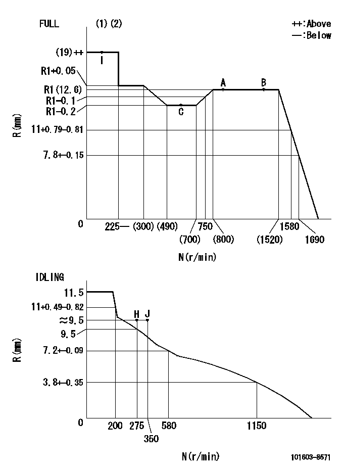
N:Pump speed
R:Rack position (mm)
(1)Torque cam stamping: T1
(2)Tolerance for racks not indicated: +-0.05mm.
----------
T1=K49
----------
----------
T1=K49
----------
Speed control lever angle

F:Full speed
I:Idle
(1)Use the pin at R = aa
(2)Stopper bolt setting
----------
aa=35mm
----------
a=10deg+-5deg b=40deg+-3deg
----------
aa=35mm
----------
a=10deg+-5deg b=40deg+-3deg
Stop lever angle

N:Pump normal
S:Stop the pump.
(1)Use the pin at R = aa
----------
aa=45mm
----------
a=12.5deg+-5deg b=40deg+-5deg
----------
aa=45mm
----------
a=12.5deg+-5deg b=40deg+-5deg
0000001501 I/P WITH LOAD PLUNGER ADJ
Plunger assembly number: PL (stamping: ST)
1. Adjustment procedures
(1)Insert the pre-stroke adjusting shims L1 for each cylinder.
(2)Adjust injection quantity.(max. var. bet. cyl. idling a1, full a2)
(3)At basic point A, adjust so that the pre-stroke is L2.
(4)Reconfirm the injection quantity.
----------
PL=131153-9020 ST=A769 L1=1mm L2=4.7+-0.05mm a1=+-14% a2=+-2.5%
----------
----------
PL=131153-9020 ST=A769 L1=1mm L2=4.7+-0.05mm a1=+-14% a2=+-2.5%
----------
Timing setting

(1)Pump vertical direction
(2)Position of timer's threaded hole at No 1 cylinder's beginning of injection
(3)B.T.D.C.: aa
(4)At rack position = bb
----------
aa=6deg bb=R1(12.6)mm
----------
a=(150deg)
----------
aa=6deg bb=R1(12.6)mm
----------
a=(150deg)
Information:
start by:a) remove air compressor 1. Remove elbow (1) and adapter. Remove the gasket, screen and gasket from behind the flange.2. Remove air compressor governor (2).3. Put a mark on the head assembly and block for correct assembly. 4. Remove six bolts (3). Remove head assembly (4). 5. Remove inlet valve springs (5) from the head assembly.6. Remove discharge valve seats (6). 7. Remove discharge valves (7). Remove springs from behind the valves. Check the discharge valve stops for wear or damage. If the discharge valve travel exceeds .057 in. (1.45 mm), make a replacement of the head assembly. 8. Remove inlet valves (8) from guides. Remove guides (9) from around the inlet valve seats. 9. Remove unloader spring (10), spring seat and spring saddle (12).10. Remove unloader plungers (11) and guides. 11. To remove unloader pistons (13) from the bore, put a cover over the inlet port, then blow air pressure in the governor mounting pad unloader port (14). 12. Check inlet valve seats (15) and unloader bore bushings (16) for damage or wear. If necessary, make a replacement. 13. Remove bolts (17). Remove cover (18) and gasket from the crankcase assembly.14. Put marks on the rod bearing caps and rods for correct assembly. 15. Remove bolts (19) and locks. Remove rod bearing caps (20). Push the pistons and rods through the top of the crankcase assembly. 16. Remove rod pin (21) from the piston. Remove rod (23).17. Remove bearings (22) from the rods and caps. 18. Use tooling (A) to remove bushing (24) from the rod. 19. Remove buttons (25) from each end of the rod pins. 20. Remove piston rings (26) from piston (27) with an approved ring expander. 21. Remove O-ring seal (29) from the crankshaft.22. Remove bolts (28). Remove adapter (30) from the crankcase assembly. 23. Remove three O-ring seals (32) from the adapter.24. Remove thrust bearing (31). 25. Use tooling (A) and a press to remove the bearing from the adapter.
Do not cause damage to the bearing surfaces of the crankshaft when it is removed from the crankcase assembly.
26. Remove crankshaft (33) from the crankcase assembly. 27. Remove bolts (34). Remove cover (35). Remove two O-ring seals from the crankcase assembly. 28. Remove O-ring seal (37) from the cover.29. Remove thrust bearing (36). 30. Remove bearing (38) from the cover.Assemble Air Compressor
1. Check all parts for damage or wear. If necessary, make a replacement with a new part.2. Make sure all parts are clean and free of dirt and foreign material. 3. Use tool (A) and a press to install the bearing in cover (1). 4. Install O-ring seal (3) on the cover.5. Install thrust bearing (2). 6. Install O-ring seals (4) in the crankcase assembly.7. Put a small amount of SAE 30 oil on the O-ring seal and install the cover on crankcase assembly (5). Tighten the bolts to a torque of 25 to 35 lb.ft. (35 to 45 N m). 8. Put crankshaft (6) in position in the crankcase assembly.
Have questions with 101603-8571?
Group cross 101603-8571 ZEXEL
Isuzu
Isuzu
101603-8571
9 400 610 663
8943959041
INJECTION-PUMP ASSEMBLY
6HH1-S
6HH1-S