Information injection-pump assembly
BOSCH
9 400 615 272
9400615272
ZEXEL
101603-8540
1016038540
ISUZU
1156030240
1156030240
Rating:
Include in #2:
104741-5440
as _
Cross reference number
BOSCH
9 400 615 272
9400615272
ZEXEL
101603-8540
1016038540
ISUZU
1156030240
1156030240
Zexel num
Bosch num
Firm num
Name
101603-8540
9 400 615 272
1156030240 ISUZU
INJECTION-PUMP ASSEMBLY
6SD1 * K
6SD1 * K
Calibration Data:
Adjustment conditions
Test oil
1404 Test oil ISO4113 or {SAEJ967d}
1404 Test oil ISO4113 or {SAEJ967d}
Test oil temperature
degC
40
40
45
Nozzle and nozzle holder
105780-8140
Bosch type code
EF8511/9A
Nozzle
105780-0000
Bosch type code
DN12SD12T
Nozzle holder
105780-2080
Bosch type code
EF8511/9
Opening pressure
MPa
17.2
Opening pressure
kgf/cm2
175
Injection pipe
Outer diameter - inner diameter - length (mm) mm 6-2-600
Outer diameter - inner diameter - length (mm) mm 6-2-600
Overflow valve
131424-4920
Overflow valve opening pressure
kPa
127
107
147
Overflow valve opening pressure
kgf/cm2
1.3
1.1
1.5
Tester oil delivery pressure
kPa
157
157
157
Tester oil delivery pressure
kgf/cm2
1.6
1.6
1.6
Direction of rotation (viewed from drive side)
Left L
Left L
Injection timing adjustment
Direction of rotation (viewed from drive side)
Left L
Left L
Injection order
1-5-3-6-
2-4
Pre-stroke
mm
3.7
3.65
3.75
Beginning of injection position
Governor side NO.1
Governor side NO.1
Difference between angles 1
Cal 1-5 deg. 60 59.5 60.5
Cal 1-5 deg. 60 59.5 60.5
Difference between angles 2
Cal 1-3 deg. 120 119.5 120.5
Cal 1-3 deg. 120 119.5 120.5
Difference between angles 3
Cal 1-6 deg. 180 179.5 180.5
Cal 1-6 deg. 180 179.5 180.5
Difference between angles 4
Cyl.1-2 deg. 240 239.5 240.5
Cyl.1-2 deg. 240 239.5 240.5
Difference between angles 5
Cal 1-4 deg. 300 299.5 300.5
Cal 1-4 deg. 300 299.5 300.5
Injection quantity adjustment
Adjusting point
-
Rack position
12
Pump speed
r/min
650
650
650
Average injection quantity
mm3/st.
91
89.4
92.6
Max. variation between cylinders
%
0
-2.5
2.5
Basic
*
Fixing the rack
*
Standard for adjustment of the maximum variation between cylinders
*
Injection quantity adjustment_02
Adjusting point
H
Rack position
9.5+-0.5
Pump speed
r/min
290
290
290
Average injection quantity
mm3/st.
11.2
9.2
13.2
Max. variation between cylinders
%
0
-14
14
Fixing the rack
*
Standard for adjustment of the maximum variation between cylinders
*
Injection quantity adjustment_03
Adjusting point
A
Rack position
R1(12)
Pump speed
r/min
650
650
650
Average injection quantity
mm3/st.
91
90
92
Basic
*
Fixing the lever
*
Injection quantity adjustment_04
Adjusting point
I
Rack position
-
Pump speed
r/min
150
150
150
Average injection quantity
mm3/st.
135
135
145
Fixing the lever
*
Rack limit
*
Timer adjustment
Pump speed
r/min
550--
Advance angle
deg.
0
0
0
Remarks
Start
Start
Timer adjustment_02
Pump speed
r/min
500
Advance angle
deg.
0.5
Timer adjustment_03
Pump speed
r/min
1250
Advance angle
deg.
4
3.5
4.5
Remarks
Finish
Finish
Test data Ex:
Governor adjustment
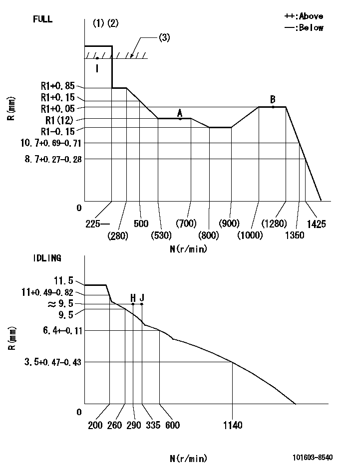
N:Pump speed
R:Rack position (mm)
(1)Torque cam stamping: T1
(2)Tolerance for racks not indicated: +-0.05mm.
(3)RACK LIMIT
----------
T1=K76
----------
----------
T1=K76
----------
Speed control lever angle

F:Full speed
I:Idle
(1)Stopper bolt setting
----------
----------
a=18deg+-5deg b=34deg+-3deg
----------
----------
a=18deg+-5deg b=34deg+-3deg
Stop lever angle
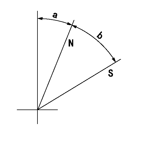
N:Pump normal
S:Stop the pump.
----------
----------
a=25deg+-5deg b=40deg+-5deg
----------
----------
a=25deg+-5deg b=40deg+-5deg
0000001501 TAMPER PROOF
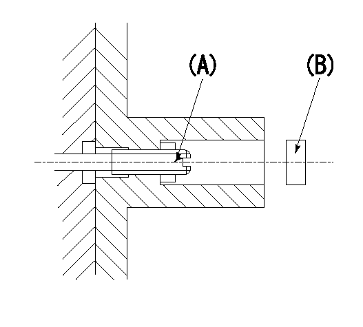
1. Set the full load.
(1)After governor adjustment (torque cam phase adjustment), move the load lever to increase the full rack position to R1.
(2)Set using the screw (A) so that the rack position is as shown above and tighten the locknut.
(3)Again set in the correct rack position using the load lever.
----------
R1=0.4mm
----------
----------
R1=0.4mm
----------
Timing setting

(1)Pump vertical direction
(2)Position of timer's threaded hole at No 1 cylinder's beginning of injection
(3)B.T.D.C.: aa
(4)-
----------
aa=18deg
----------
a=(40deg)
----------
aa=18deg
----------
a=(40deg)
Information:
Engine Crankshaft Turns Freely
Exhaust Smoke Can Be Seen While Starting Recommended Procedure
1. Cold Outside Temperatures ... It can be necessary to use starting aids, or to heat engine oil or coolant at temperatures below 10°F (-12°C).2. Air in Fuel System ... With air in the fuel system, the engine will normally be difficult to start, run rough, and release a large amount of white smoke. If the engine will not start, loosen a fuel injection line nut at the valve cover base. With the governor lever in the shutoff position, operate the fuel priming pump until the flow of fuel from the loosened fuel injection line is free of air. Tighten the fuel line nut. Fasten the priming pump and start the engine. If the engine still does not run smooth or releases a large amount of white smoke, loosen the fuel line nuts one at a time at the valve cover base until the fuel that comes out is free of air. Tighten the fuel line nuts. If the air can not be removed in this way, put 5 psi (35 kPa) of air pressure to the fuel tank.
Do not use more than 8 psi (55 kPa) of air pressure in the fuel tank or damage to the tank may result.
Check for leakage at the connections between the fuel tank and the fuel transfer pump. If leaks are found, tighten the connections or replace the lines. If there are no visual leaks, remove the fuel supply line from the tank and connect it to an outside fuel supply. If this corrects the problem, the suction line (standpipe) inside the fuel tank has a leak.3. Low Quality Fuel ... Remove a small amount of fuel from the tank and check for water in the fuel. If there is water in the fuel, remove fuel from the tank until it is free of water and fill with a good quality fuel. Change the fuel filter and "prime" (remove the air and/or low quality fuel from the fuel system) the fuel system with the fuel priming pump. If there is no water in the fuel, prime and start the engine by using an outside source of fuel. If engine starts correctly using different fuel, remove all fuel from the tank and fill with good quality fuel. Prime the fuel system if necessary.4. Low Fuel Pressure ... Change the fuel filter. If the pressure is still low, check the bypass valve in the fuel transfer pump. Debris in the system can make the valve become stationary in the open position.5. Fuel Injection Timing Not Correct ... Check and make necessary adjustments as per Testing
Have questions with 101603-8540?
Group cross 101603-8540 ZEXEL
Isuzu
101603-8540
9 400 615 272
1156030240
INJECTION-PUMP ASSEMBLY
6SD1
6SD1