Information injection-pump assembly
ZEXEL
101603-8520
1016038520
ISUZU
8943957540
8943957540
Rating:
Service parts 101603-8520 INJECTION-PUMP ASSEMBLY:
1.
_

7.
COUPLING PLATE
8.
_
9.
_
11.
Nozzle and Holder
12.
Open Pre:MPa(Kqf/cm2)
16.2{165}/18.1{185}

15.
NOZZLE SET
Include in #1:
101603-8520
as INJECTION-PUMP ASSEMBLY
Include in #2:
104741-5461
as _
Cross reference number
ZEXEL
101603-8520
1016038520
ISUZU
8943957540
8943957540
Zexel num
Bosch num
Firm num
Name
Calibration Data:
Adjustment conditions
Test oil
1404 Test oil ISO4113 or {SAEJ967d}
1404 Test oil ISO4113 or {SAEJ967d}
Test oil temperature
degC
40
40
45
Nozzle and nozzle holder
105780-8140
Bosch type code
EF8511/9A
Nozzle
105780-0000
Bosch type code
DN12SD12T
Nozzle holder
105780-2080
Bosch type code
EF8511/9
Opening pressure
MPa
17.2
Opening pressure
kgf/cm2
175
Injection pipe
Outer diameter - inner diameter - length (mm) mm 6-2-600
Outer diameter - inner diameter - length (mm) mm 6-2-600
Overflow valve
131424-4920
Overflow valve opening pressure
kPa
127
107
147
Overflow valve opening pressure
kgf/cm2
1.3
1.1
1.5
Tester oil delivery pressure
kPa
157
157
157
Tester oil delivery pressure
kgf/cm2
1.6
1.6
1.6
Direction of rotation (viewed from drive side)
Left L
Left L
Injection timing adjustment
Direction of rotation (viewed from drive side)
Left L
Left L
Injection order
1-5-3-6-
2-4
Pre-stroke
mm
4.7
4.65
4.75
Rack position
After adjusting injection quantity. R=A
After adjusting injection quantity. R=A
Beginning of injection position
Governor side NO.1
Governor side NO.1
Difference between angles 1
Cal 1-5 deg. 60 59.5 60.5
Cal 1-5 deg. 60 59.5 60.5
Difference between angles 2
Cal 1-3 deg. 120 119.5 120.5
Cal 1-3 deg. 120 119.5 120.5
Difference between angles 3
Cal 1-6 deg. 180 179.5 180.5
Cal 1-6 deg. 180 179.5 180.5
Difference between angles 4
Cyl.1-2 deg. 240 239.5 240.5
Cyl.1-2 deg. 240 239.5 240.5
Difference between angles 5
Cal 1-4 deg. 300 299.5 300.5
Cal 1-4 deg. 300 299.5 300.5
Injection quantity adjustment
Adjusting point
-
Rack position
13
Pump speed
r/min
850
850
850
Average injection quantity
mm3/st.
86.5
84.9
88.1
Max. variation between cylinders
%
0
-2.5
2.5
Basic
*
Fixing the rack
*
Standard for adjustment of the maximum variation between cylinders
*
Injection quantity adjustment_02
Adjusting point
-
Rack position
9.6+-0.5
Pump speed
r/min
275
275
275
Average injection quantity
mm3/st.
9.4
8.1
10.7
Max. variation between cylinders
%
0
-14
14
Fixing the rack
*
Standard for adjustment of the maximum variation between cylinders
*
Remarks
Adjust only variation between cylinders; adjust governor according to governor specifications.
Adjust only variation between cylinders; adjust governor according to governor specifications.
Injection quantity adjustment_03
Adjusting point
A
Rack position
R1(13)
Pump speed
r/min
850
850
850
Average injection quantity
mm3/st.
86.5
85.5
87.5
Basic
*
Fixing the lever
*
Injection quantity adjustment_04
Adjusting point
B
Rack position
R1+0.15
Pump speed
r/min
1450
1450
1450
Average injection quantity
mm3/st.
95.5
92.3
98.7
Fixing the lever
*
Injection quantity adjustment_05
Adjusting point
C
Rack position
R1-0.25
Pump speed
r/min
600
600
600
Average injection quantity
mm3/st.
77.5
74.3
80.7
Fixing the lever
*
Timer adjustment
Pump speed
r/min
905--
Advance angle
deg.
0
0
0
Load
3/5
Remarks
Start
Start
Timer adjustment_02
Pump speed
r/min
855
Advance angle
deg.
0.3
Load
3/5
Timer adjustment_03
Pump speed
r/min
1110
Advance angle
deg.
1.5
1
2
Load
3/5
Timer adjustment_04
Pump speed
r/min
-
Advance angle
deg.
1.5
1
2
Load
5/5
Remarks
Measure the actual speed.
Measure the actual speed.
Timer adjustment_05
Pump speed
r/min
1450
Advance angle
deg.
7
6.5
7.5
Load
5/5
Remarks
Finish
Finish
Test data Ex:
Governor adjustment
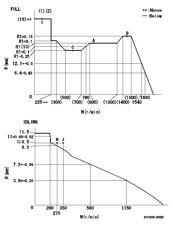
N:Pump speed
R:Rack position (mm)
(1)Torque cam stamping: T1
(2)Tolerance for racks not indicated: +-0.05mm.
----------
T1=K09
----------
----------
T1=K09
----------
Speed control lever angle

F:Full speed
I:Idle
(1)Use the pin at R = aa
(2)Stopper bolt set position 'H'
----------
aa=35mm
----------
a=10deg+-5deg b=40deg+-3deg
----------
aa=35mm
----------
a=10deg+-5deg b=40deg+-3deg
Stop lever angle

N:Pump normal
S:Stop the pump.
(1)Use the pin at R = aa
----------
aa=45mm
----------
a=12.5deg+-5deg b=40deg+-5deg
----------
aa=45mm
----------
a=12.5deg+-5deg b=40deg+-5deg
0000001501 AIR CYLINDER
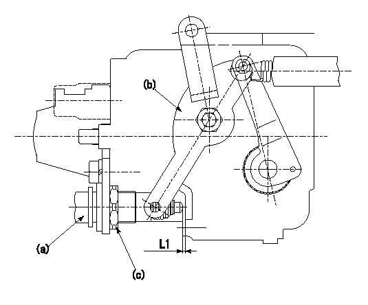
(a) Air cylinder
(b) Speed lever
(c) Lock nut
1. Air cylinder adjustment procedure
(1)Fix the speed lever (b) at the idle side.
(2)Screw in the air cylinder (a)
(3)Set the clearance between the speed lever (b) and the air cylinder (a) to approximately L1.
----------
L1=(1) mm
----------
----------
L1=(1) mm
----------
0000001601 I/P WITH LOAD PLUNGER ADJ
Plunger assembly number: PL (stamping: ST)
1. Adjustment procedures
(1)Insert the pre-stroke adjusting shims L1 for each cylinder.
(2)Adjust injection quantity.(max. var. bet. cyl. idling a1, full a2)
(3)At basic point A, adjust so that the pre-stroke is L2.
(4)Reconfirm the injection quantity.
----------
PL=131153-9020 ST=A769 L1=1mm L2=4.7+-0.05mm a1=+-14% a2=+-2.5%
----------
----------
PL=131153-9020 ST=A769 L1=1mm L2=4.7+-0.05mm a1=+-14% a2=+-2.5%
----------
Timing setting

(1)Pump vertical direction
(2)Position of timer's threaded hole at No 1 cylinder's beginning of injection
(3)B.T.D.C.: aa
(4)At rack position = bb
----------
aa=6deg bb=13mm
----------
a=(150deg)
----------
aa=6deg bb=13mm
----------
a=(150deg)
Information:
High Fuel Consumption (Diagnosis with Chassis Dynamometer) (Diagnosis with Chassis Dynamometer)1. Preparation of vehicle for fuel consumption test (consult dynamometer manufacturer's operating instructions for specific details on correct operation). Always perform the Primary Engine Test procedure before vehicle is installed on chassis dynamometer.a. Place vehicle on the chassis dynamometer. Tie the vehicle in a way that will not add any load to the drive wheels. Do not pull wheels down into dynamometer drive rolls.Check the radiator coolant level, crankcase oil level, tire pressure, tire condition, remove rocks from the tire tread and connect exhaust system.
Recapped tires should be run on a chassis dynamometer only at the customer's own risk.
b. The maximum acceptable fuel rate must be calculated for the customer's engine by use of the formula that follows: Find the rated brake specific fuel consumption (lb-bhp/hr) from the RACK SETTING INFORMATION and add .010 manufacturing tolerance. Multiply this value by the advertised engine horsepower (plus 3% manf. tol.) and divide by the density of the fuel (lbs/gal).c. Calculate the allowable limits that the customer can expect from his engine and present these figures to him. Caterpillar engines are rated with the conditions that follow: Measure and record these variables. Advertised engine bhp (less 3% manufacturing tolerance) can then be corrected to test conditions by use of procedure and correction tables found in Special Instruction GEG01024.2. Operate vehicle at 60% of rated speed with moderate load until oil and coolant temperatures reach their normal range for operation.
If there is a heavy vibration, drive shaft whip, tire bounce, etc., do not continue with dynamometer test until cause of the problem is corrected. Engines that have had new internal parts installed should be operated on a run-in schedule before operation at full load.
Put transmission in direct gear and the differential in the highest speed ratio. Operate vehicle at maximum engine speed and increase chassis dynamometer load until a speed of 50 rpm less than rated speed is reached (continuity light should be on). Maintain this speed for one minute and record the engine speed, wheel horsepower and fuel rate.3. If the fuel rate and the wheel horsepower are both acceptable, then the engine is not the cause of the complaint, or the complaint is not valid. Refer to section PROBLEM WITH VEHICLE OR VEHICLE OPERATION.4. If the wheel horsepower is low, regardless of how the fuel rate measures, refer to the LOW POWER TROUBLESHOOTING CHART. The low power problem must be corrected first.5. If fuel rate and wheel horsepower are both too high, check the balance point of the engine (speed at which the rack adjustment screw just touches the torque spring or stop bar). At this point the continuity light should flicker (go off and on dimly).If the balance point is high, the high idle will have to be decreased to lower the balance point to the correct rpm (point at which the continuity light just comes on). If the balance point is correct, see Procedure No. 8.6. If the