Information injection-pump assembly
BOSCH
9 400 619 951
9400619951
ZEXEL
101603-8510
1016038510
ISUZU
8943957530
8943957530
Rating:
Service parts 101603-8510 INJECTION-PUMP ASSEMBLY:
1.
_

7.
COUPLING PLATE
8.
_
9.
_
11.
Nozzle and Holder
12.
Open Pre:MPa(Kqf/cm2)
16.2{165}/18.1{185}

15.
NOZZLE SET
Include in #1:
101603-8510
as INJECTION-PUMP ASSEMBLY
Include in #2:
104741-5422
as _
Cross reference number
BOSCH
9 400 619 951
9400619951
ZEXEL
101603-8510
1016038510
ISUZU
8943957530
8943957530
Zexel num
Bosch num
Firm num
Name
Calibration Data:
Adjustment conditions
Test oil
1404 Test oil ISO4113 or {SAEJ967d}
1404 Test oil ISO4113 or {SAEJ967d}
Test oil temperature
degC
40
40
45
Nozzle and nozzle holder
105480-8140
Bosch type code
EF8511/9
Nozzle
105780-0000
Bosch type code
DN12SD12T
Nozzle holder
105780-2080
Bosch type code
EF8511/9
Opening pressure
MPa
17.2
Opening pressure
kgf/cm2
175
Injection pipe
Outer diameter - inner diameter - length (mm) mm 6-2-600
Outer diameter - inner diameter - length (mm) mm 6-2-600
Overflow valve
131424-4920
Overflow valve opening pressure
kPa
127
107
147
Overflow valve opening pressure
kgf/cm2
1.3
1.1
1.5
Tester oil delivery pressure
kPa
157
157
157
Tester oil delivery pressure
kgf/cm2
1.6
1.6
1.6
Direction of rotation (viewed from drive side)
Left L
Left L
Injection timing adjustment
Direction of rotation (viewed from drive side)
Left L
Left L
Injection order
1-5-3-6-
2-4
Pre-stroke
mm
4.7
4.65
4.75
Rack position
After adjusting injection quantity. R=A
After adjusting injection quantity. R=A
Beginning of injection position
Governor side NO.1
Governor side NO.1
Difference between angles 1
Cal 1-5 deg. 60 59.5 60.5
Cal 1-5 deg. 60 59.5 60.5
Difference between angles 2
Cal 1-3 deg. 120 119.5 120.5
Cal 1-3 deg. 120 119.5 120.5
Difference between angles 3
Cal 1-6 deg. 180 179.5 180.5
Cal 1-6 deg. 180 179.5 180.5
Difference between angles 4
Cyl.1-2 deg. 240 239.5 240.5
Cyl.1-2 deg. 240 239.5 240.5
Difference between angles 5
Cal 1-4 deg. 300 299.5 300.5
Cal 1-4 deg. 300 299.5 300.5
Injection quantity adjustment
Adjusting point
-
Rack position
13
Pump speed
r/min
850
850
850
Average injection quantity
mm3/st.
86.5
84.9
88.1
Max. variation between cylinders
%
0
-2.5
2.5
Basic
*
Fixing the rack
*
Standard for adjustment of the maximum variation between cylinders
*
Injection quantity adjustment_02
Adjusting point
-
Rack position
9.6+-0.5
Pump speed
r/min
275
275
275
Average injection quantity
mm3/st.
9.4
8.1
10.7
Max. variation between cylinders
%
0
-14
14
Fixing the rack
*
Standard for adjustment of the maximum variation between cylinders
*
Remarks
Adjust only variation between cylinders; adjust governor according to governor specifications.
Adjust only variation between cylinders; adjust governor according to governor specifications.
Injection quantity adjustment_03
Adjusting point
A
Rack position
R1(13)
Pump speed
r/min
850
850
850
Average injection quantity
mm3/st.
86.5
85.5
87.5
Basic
*
Fixing the lever
*
Injection quantity adjustment_04
Adjusting point
B
Rack position
R1+0.15
Pump speed
r/min
1450
1450
1450
Average injection quantity
mm3/st.
95.5
92.3
98.7
Fixing the lever
*
Injection quantity adjustment_05
Adjusting point
C
Rack position
R1-0.25
Pump speed
r/min
600
600
600
Average injection quantity
mm3/st.
77.5
74.3
80.7
Fixing the lever
*
Timer adjustment
Pump speed
r/min
905--
Advance angle
deg.
0
0
0
Load
3/5
Remarks
Start
Start
Timer adjustment_02
Pump speed
r/min
855
Advance angle
deg.
0.3
Load
3/5
Timer adjustment_03
Pump speed
r/min
-
Advance angle
deg.
1.5
1
2
Load
5/5
Remarks
Measure the actual speed.
Measure the actual speed.
Timer adjustment_04
Pump speed
r/min
1110
Advance angle
deg.
1.5
1
2
Load
3/5
Timer adjustment_05
Pump speed
r/min
1450
Advance angle
deg.
7
6.5
7.5
Load
5/5
Remarks
Finish
Finish
Test data Ex:
Governor adjustment
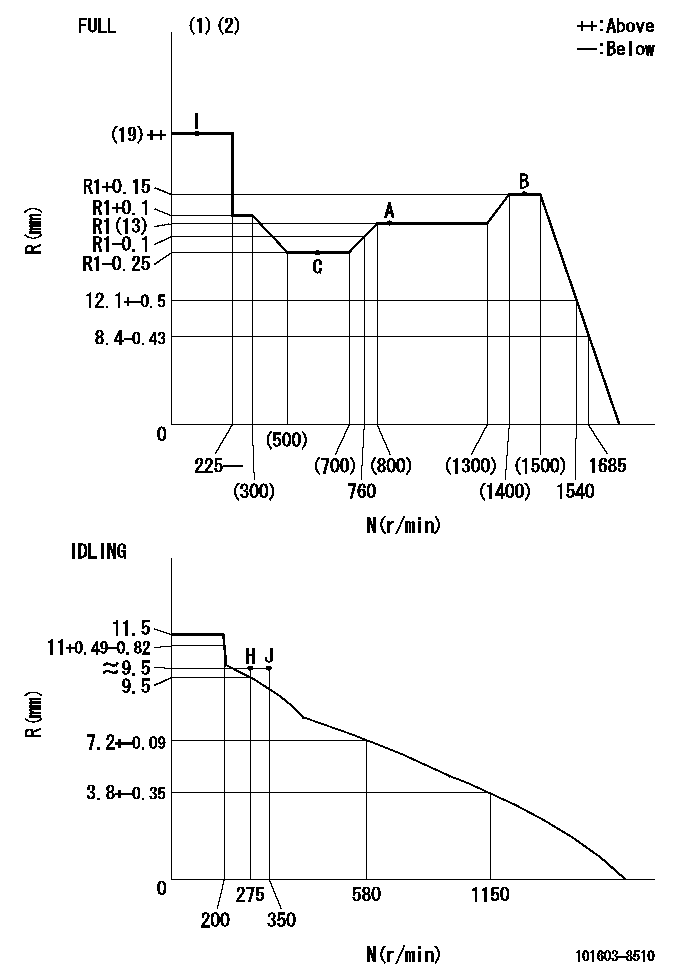
N:Pump speed
R:Rack position (mm)
(1)Torque cam stamping: T1
(2)Tolerance for racks not indicated: +-0.05mm.
----------
T1=K09
----------
----------
T1=K09
----------
Speed control lever angle

F:Full speed
I:Idle
(1)Use the hole at R = aa
(2)Stopper bolt set position 'H'
----------
aa=43mm
----------
a=5deg+-5deg b=40deg+-3deg
----------
aa=43mm
----------
a=5deg+-5deg b=40deg+-3deg
Stop lever angle

N:Pump normal
S:Stop the pump.
(1)Use the pin at R = aa
----------
aa=45mm
----------
a=12.5deg+-5deg b=40deg+-5deg
----------
aa=45mm
----------
a=12.5deg+-5deg b=40deg+-5deg
0000001501 I/P WITH LOAD PLUNGER ADJ
Plunger assembly number: PL (stamping: ST)
1. Adjustment procedures
(1)Insert the pre-stroke adjusting shims L1 for each cylinder.
(2)Adjust injection quantity.(max. var. bet. cyl. idling a1, full a2)
(3)At basic point A, adjust so that the pre-stroke is L2.
(4)Reconfirm the injection quantity.
----------
PL=131153-9020 ST=A769 L1=1mm L2=4.7+-0.05mm a1=+-14% a2=+-2.5%
----------
----------
PL=131153-9020 ST=A769 L1=1mm L2=4.7+-0.05mm a1=+-14% a2=+-2.5%
----------
0000001601 AIR CYLINDER

1. (1) Set the speed lever to idle.
(2)Screw in air cylinder (A)
(3)Set the clearance from the speed lever (B) at approximately L.
----------
L=1mm
----------
----------
L=1mm
----------
Timing setting

(1)Pump vertical direction
(2)Position of timer's threaded hole at No 1 cylinder's beginning of injection
(3)B.T.D.C.: aa
(4)At rack position = bb
----------
aa=6deg bb=R1(13)mm
----------
a=(150deg)
----------
aa=6deg bb=R1(13)mm
----------
a=(150deg)
Information:
Primary Engine Test For Low Power 1. The customer must be asked many questions to determine whether his complaint is valid, or whether his diagnosis of an actual problem is correct.Some of the questions that must be asked are as follows:a. Does poor performance occur when the vehicle is operated at steady speed on a level road surface, or when vehicle is pulled up a grade? A positive response to either or both of the above conditions would indicate a low power (steady state) problem. Begin with Low Power Diagnosis.b. Does the poor performance always occur under the same conditions or is the problem intermittent (happens only occasionally)? This is a very important line of questioning to pursue. Any constant performance problem can normally be identified and the problem corrected. If an intermittent problem exists, the mechanic must be aware that the condition is only occasional, and must run certain tests several times in an attempt to force the malfunction condition. If the condition is not duplicated, the diagnosis that no problem exists will be incorrect, and the vehicle operator will again be confronted with the problem somewhere out on the road.c. Was the engine running rough or misfiring when the poor performance was noticed? A positive response to this question will indicate the need to isolate the bad cylinder(s) and correct the problem. See section Cylinder Misfire.2. Check the crankcase oil level and the coolant level of the radiator. Remove the boost air line from the AFRC (air-fuel ratio control) during the Primary Engine Test. This will prevent the AFRC from becoming pnuematically activated during the checks. If activated, the AFRC could give an indication of a problem when there is none.3. A slightly lower rpm (15 rpm below low limit) should be expected for the engine in vehicle than the rpm shown in the RACK SETTING INFORMATION. This is caused by the parasitic loads of the engine accessories involved.4. With the engine running, the throttle must have enough travel for the governor control lever to break over (go past the normal governor stop for high idle position) a small amount when the throttle pedal is fully depressed. If full travel is not available, disconnect throttle linkage from governor lever. With throttle linkage disconnected, full travel of governor lever will indicate linkage problems, and the linkage will have to be adjusted. Limited travel of the governor lever will indicte a problem within the governor.5. Only a mechanic with the correct training should change the high idle setting. The procedure is given in the Service Manual under the subject GOVERNOR ADJUSTMENTS.6. If high idle rpm can not be made correct with the high idle adjustment screw, there is a problem inside the governor. Disassemble the governor and check for damaged parts or wrong parts installed in the governor. Some common problems are worn bushings, worn spring seat, or a broken or wrong governor spring.7. Before 8S4627 Circuit Tester is installed, be sure to test the light for correct