Information injection-pump assembly
BOSCH
9 400 615 269
9400615269
ZEXEL
101603-8493
1016038493
ISUZU
8943957513
8943957513

Rating:
Include in #2:
104741-5402
as _
Cross reference number
BOSCH
9 400 615 269
9400615269
ZEXEL
101603-8493
1016038493
ISUZU
8943957513
8943957513
Zexel num
Bosch num
Firm num
Name
101603-8493
9 400 615 269
8943957513 ISUZU
INJECTION-PUMP ASSEMBLY
6HH1-S K
6HH1-S K
Calibration Data:
Adjustment conditions
Test oil
1404 Test oil ISO4113 or {SAEJ967d}
1404 Test oil ISO4113 or {SAEJ967d}
Test oil temperature
degC
40
40
45
Nozzle and nozzle holder
105780-8140
Bosch type code
EF8511/9A
Nozzle
105780-0000
Bosch type code
DN12SD12T
Nozzle holder
105780-2080
Bosch type code
EF8511/9
Opening pressure
MPa
17.2
Opening pressure
kgf/cm2
175
Injection pipe
Outer diameter - inner diameter - length (mm) mm 6-2-600
Outer diameter - inner diameter - length (mm) mm 6-2-600
Overflow valve
131424-4920
Overflow valve opening pressure
kPa
127
107
147
Overflow valve opening pressure
kgf/cm2
1.3
1.1
1.5
Tester oil delivery pressure
kPa
157
157
157
Tester oil delivery pressure
kgf/cm2
1.6
1.6
1.6
Direction of rotation (viewed from drive side)
Left L
Left L
Injection timing adjustment
Direction of rotation (viewed from drive side)
Left L
Left L
Injection order
1-5-3-6-
2-4
Pre-stroke
mm
4.7
4.65
4.75
Rack position
After adjusting injection quantity. R=A
After adjusting injection quantity. R=A
Beginning of injection position
Governor side NO.1
Governor side NO.1
Difference between angles 1
Cal 1-5 deg. 60 59.5 60.5
Cal 1-5 deg. 60 59.5 60.5
Difference between angles 2
Cal 1-3 deg. 120 119.5 120.5
Cal 1-3 deg. 120 119.5 120.5
Difference between angles 3
Cal 1-6 deg. 180 179.5 180.5
Cal 1-6 deg. 180 179.5 180.5
Difference between angles 4
Cyl.1-2 deg. 240 239.5 240.5
Cyl.1-2 deg. 240 239.5 240.5
Difference between angles 5
Cal 1-4 deg. 300 299.5 300.5
Cal 1-4 deg. 300 299.5 300.5
Injection quantity adjustment
Adjusting point
-
Rack position
13
Pump speed
r/min
850
850
850
Average injection quantity
mm3/st.
86.5
84.9
88.1
Max. variation between cylinders
%
0
-2.5
2.5
Basic
*
Fixing the rack
*
Standard for adjustment of the maximum variation between cylinders
*
Injection quantity adjustment_02
Adjusting point
-
Rack position
9.6+-0.5
Pump speed
r/min
275
275
275
Average injection quantity
mm3/st.
9.4
8.1
10.7
Max. variation between cylinders
%
0
-14
14
Fixing the rack
*
Standard for adjustment of the maximum variation between cylinders
*
Remarks
Adjust only variation between cylinders; adjust governor according to governor specifications.
Adjust only variation between cylinders; adjust governor according to governor specifications.
Injection quantity adjustment_03
Adjusting point
A
Rack position
R1(13)
Pump speed
r/min
850
850
850
Average injection quantity
mm3/st.
86.5
85.5
87.5
Basic
*
Fixing the lever
*
Injection quantity adjustment_04
Adjusting point
B
Rack position
R1+0.15
Pump speed
r/min
1450
1450
1450
Average injection quantity
mm3/st.
95.5
92.3
98.7
Fixing the lever
*
Injection quantity adjustment_05
Adjusting point
C
Rack position
R1-0.25
Pump speed
r/min
600
600
600
Average injection quantity
mm3/st.
77.5
74.3
80.7
Fixing the lever
*
Timer adjustment
Pump speed
r/min
905--
Advance angle
deg.
0
0
0
Load
3/5
Remarks
Start
Start
Timer adjustment_02
Pump speed
r/min
855
Advance angle
deg.
0.3
Load
3/5
Timer adjustment_03
Pump speed
r/min
-
Advance angle
deg.
1.5
1
2
Load
5/5
Remarks
Measure the actual speed.
Measure the actual speed.
Timer adjustment_04
Pump speed
r/min
1110
Advance angle
deg.
1.5
1
2
Load
3/5
Timer adjustment_05
Pump speed
r/min
1450
Advance angle
deg.
7
6.5
7.5
Load
5/5
Remarks
Finish
Finish
Test data Ex:
Governor adjustment
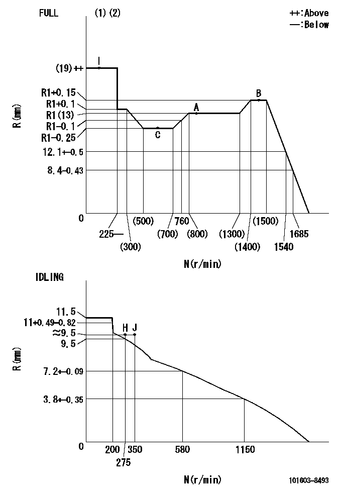
N:Pump speed
R:Rack position (mm)
(1)Torque cam stamping: T1
(2)Tolerance for racks not indicated: +-0.05mm.
----------
T1=K09
----------
----------
T1=K09
----------
Speed control lever angle
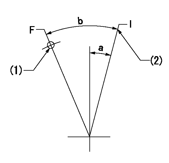
F:Full speed
I:Idle
(1)Use the hole at R = aa
(2)Stopper bolt set position 'H'
----------
aa=35mm
----------
a=14deg+-5deg b=40deg+-3deg
----------
aa=35mm
----------
a=14deg+-5deg b=40deg+-3deg
Stop lever angle
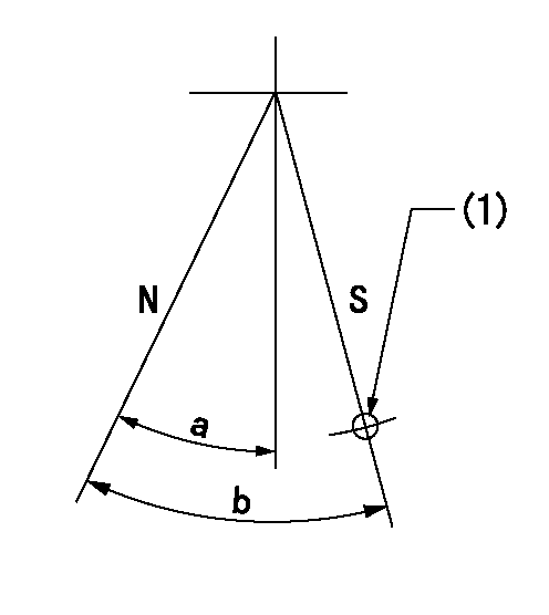
N:Pump normal
S:Stop the pump.
(1)Use the pin at R = aa
----------
aa=46.5mm
----------
a=34.5deg+-5deg b=40deg+-5deg
----------
aa=46.5mm
----------
a=34.5deg+-5deg b=40deg+-5deg
0000001501 I/P WITH LOAD PLUNGER ADJ
Plunger assembly number: PL (stamping: ST)
1. Adjustment procedures
(1)Insert the pre-stroke adjusting shims L1 for each cylinder.
(2)Adjust injection quantity.(max. var. bet. cyl. idling a1, full a2)
(3)At basic point A, adjust so that the pre-stroke is L2.
(4)Reconfirm the injection quantity.
----------
PL=131153-9020 ST=A769 L1=1mm L2=4.7+-0.05mm a1=+-14% a2=+-2.5%
----------
----------
PL=131153-9020 ST=A769 L1=1mm L2=4.7+-0.05mm a1=+-14% a2=+-2.5%
----------
Timing setting

(1)Pump vertical direction
(2)Position of timer's threaded hole at No 1 cylinder's beginning of injection
(3)B.T.D.C.: aa
(4)At rack position = bb
----------
aa=6deg bb=R1(13)mm
----------
a=(150deg)
----------
aa=6deg bb=R1(13)mm
----------
a=(150deg)
Information:
(1) Thickness of top plate ... .338 .001 in.(8.59 0.03 mm) Thickness of gasket that is placed between top plate and cylinder block ... .008 .001 in.(0.20 0.03 mm)Height of liner over top plate, under installation pressure ... .005 .003 in.(0.13 0.08 mm)(2) Height of dowels above top surface of cylinder block ... .73 in.(18.5 mm)(3) Dimension (new) from centerline of crankshaft bearing bore to top of block (top deck) ... 16.750 .006 in.(425.45 0.15 mm)(4) Bore in block for camshaft bearings ... 3.0250 .0007 in.(76.835 0.018 mm)(5) Bore in the block for the main bearings: standard, original size (new) ... 5.1138 .0005 in.(129.891 0.013 mm).025 in. (0.64 mm) larger than original size ... 5.1388 .0005 in.(130.526 0.013 mm)(6) Distance from front or rear face of cylinder block to end of dowels ... .75 in.(19.1 mm)(7) Width of main bearing cap ... 8.5000 .0005 in.(215.900 0.013 mm) Width of block for main bearing cap ... 8.5000 .0005 in.(215.900 0.013 mm)Clearance between main bearing cap and cylinder block ... .001 in.(0.03 mm) tight to ... .001 in.(0.03 mm) loose
Tightening Procedure For Main Bearings(8) Torque for the bolts that hold the caps for the main bearings: Install the main bearing caps with the marks (arrow) toward the front of the engine. Install each cap in the correct position by putting the number stamped on the bottom of the cap toward the corresponding number on the cylinder block.a. Put engine oil on the threads of the bolts.b. Tighten the bolts first on the tab side of the cap to ... 190 10 lb. ft.(260 14 N m)c. Tighten the bolts on the opposite side to ... 190 10 lb. ft.(260 14 N m)d. Put a mark on each bolt and cap as shown.e. Tighten the bolts on the opposite side, from the mark ... 120°f. Tighten the bolts on the tab side of the cap, from the mark ... 120°(9) Dimension (new) from centerline of crankshaft bearing bore to bottom of block (pan rails) ... 6.500 .004 in.(165.10 0.10 mm) (10) Put 9S3264 Pipe Sealant on threads of 14 plugs before installation in the cylinder block.(11) Torque for bolts holding oil jet cooling tubes (later engines) ... 18 5 lb. ft.(24 7 N m)
Tightening Procedure For Main Bearings(8) Torque for the bolts that hold the caps for the main bearings: Install the main bearing caps with the marks (arrow) toward the front of the engine. Install each cap in the correct position by putting the number stamped on the bottom of the cap toward the corresponding number on the cylinder block.a. Put engine oil on the threads of the bolts.b. Tighten the bolts first on the tab side of the cap to ... 190 10 lb. ft.(260 14 N m)c. Tighten the bolts on the opposite side to ... 190 10 lb. ft.(260 14 N m)d. Put a mark on each bolt and cap as shown.e. Tighten the bolts on the opposite side, from the mark ... 120°f. Tighten the bolts on the tab side of the cap, from the mark ... 120°(9) Dimension (new) from centerline of crankshaft bearing bore to bottom of block (pan rails) ... 6.500 .004 in.(165.10 0.10 mm) (10) Put 9S3264 Pipe Sealant on threads of 14 plugs before installation in the cylinder block.(11) Torque for bolts holding oil jet cooling tubes (later engines) ... 18 5 lb. ft.(24 7 N m)
Have questions with 101603-8493?
Group cross 101603-8493 ZEXEL
Isuzu
101603-8493
9 400 615 269
8943957513
INJECTION-PUMP ASSEMBLY
6HH1-S
6HH1-S