Information injection-pump assembly
ZEXEL
101603-8490
1016038490
ISUZU
8943957510
8943957510

Rating:
Service parts 101603-8490 INJECTION-PUMP ASSEMBLY:
1.
_

7.
COUPLING PLATE
8.
_
9.
_
11.
Nozzle and Holder
8-94393-335-1
12.
Open Pre:MPa(Kqf/cm2)
16.2{165}/18.1{185}

15.
NOZZLE SET
Include in #1:
101603-8490
as INJECTION-PUMP ASSEMBLY
Include in #2:
104741-5391
as _
Cross reference number
ZEXEL
101603-8490
1016038490
ISUZU
8943957510
8943957510
Zexel num
Bosch num
Firm num
Name
Calibration Data:
Adjustment conditions
Test oil
1404 Test oil ISO4113 or {SAEJ967d}
1404 Test oil ISO4113 or {SAEJ967d}
Test oil temperature
degC
40
40
45
Nozzle and nozzle holder
105780-8140
Bosch type code
EF8511/9A
Nozzle
105780-0000
Bosch type code
DN12SD12T
Nozzle holder
105780-2080
Bosch type code
EF8511/9
Opening pressure
MPa
17.2
Opening pressure
kgf/cm2
175
Injection pipe
Outer diameter - inner diameter - length (mm) mm 6-2-600
Outer diameter - inner diameter - length (mm) mm 6-2-600
Overflow valve
131424-4920
Overflow valve opening pressure
kPa
127
107
147
Overflow valve opening pressure
kgf/cm2
1.3
1.1
1.5
Tester oil delivery pressure
kPa
157
157
157
Tester oil delivery pressure
kgf/cm2
1.6
1.6
1.6
Direction of rotation (viewed from drive side)
Left L
Left L
Injection timing adjustment
Direction of rotation (viewed from drive side)
Left L
Left L
Injection order
1-5-3-6-
2-4
Pre-stroke
mm
4.7
4.65
4.75
Rack position
After adjusting injection quantity. R=A
After adjusting injection quantity. R=A
Beginning of injection position
Governor side NO.1
Governor side NO.1
Difference between angles 1
Cal 1-5 deg. 60 59.5 60.5
Cal 1-5 deg. 60 59.5 60.5
Difference between angles 2
Cal 1-3 deg. 120 119.5 120.5
Cal 1-3 deg. 120 119.5 120.5
Difference between angles 3
Cal 1-6 deg. 180 179.5 180.5
Cal 1-6 deg. 180 179.5 180.5
Difference between angles 4
Cyl.1-2 deg. 240 239.5 240.5
Cyl.1-2 deg. 240 239.5 240.5
Difference between angles 5
Cal 1-4 deg. 300 299.5 300.5
Cal 1-4 deg. 300 299.5 300.5
Injection quantity adjustment
Adjusting point
-
Rack position
13
Pump speed
r/min
850
850
850
Average injection quantity
mm3/st.
86.5
84.9
88.1
Max. variation between cylinders
%
0
-2.5
2.5
Basic
*
Fixing the rack
*
Standard for adjustment of the maximum variation between cylinders
*
Injection quantity adjustment_02
Adjusting point
-
Rack position
9.6+-0.5
Pump speed
r/min
275
275
275
Average injection quantity
mm3/st.
9.4
8.1
10.7
Max. variation between cylinders
%
0
-14
14
Fixing the rack
*
Standard for adjustment of the maximum variation between cylinders
*
Remarks
Adjust only variation between cylinders; adjust governor according to governor specifications.
Adjust only variation between cylinders; adjust governor according to governor specifications.
Injection quantity adjustment_03
Adjusting point
A
Rack position
R1(13)
Pump speed
r/min
850
850
850
Average injection quantity
mm3/st.
86.5
85.5
87.5
Basic
*
Fixing the lever
*
Injection quantity adjustment_04
Adjusting point
B
Rack position
R1+0.15
Pump speed
r/min
1450
1450
1450
Average injection quantity
mm3/st.
95.5
92.3
98.7
Fixing the lever
*
Injection quantity adjustment_05
Adjusting point
C
Rack position
R1-0.25
Pump speed
r/min
600
600
600
Average injection quantity
mm3/st.
77.5
74.3
80.7
Fixing the lever
*
Timer adjustment
Pump speed
r/min
905--
Advance angle
deg.
0
0
0
Load
3/5
Remarks
Start
Start
Timer adjustment_02
Pump speed
r/min
855
Advance angle
deg.
0.3
Load
3/5
Timer adjustment_03
Pump speed
r/min
-
Advance angle
deg.
1.5
1
2
Load
5/5
Remarks
Measure the actual speed.
Measure the actual speed.
Timer adjustment_04
Pump speed
r/min
1110
Advance angle
deg.
1.5
1
2
Load
3/5
Timer adjustment_05
Pump speed
r/min
1450
Advance angle
deg.
7
6.5
7.5
Load
5/5
Remarks
Finish
Finish
Test data Ex:
Governor adjustment
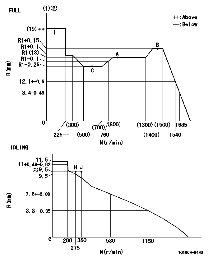
N:Pump speed
R:Rack position (mm)
(1)Torque cam stamping: T1
(2)Tolerance for racks not indicated: +-0.05mm.
----------
T1=K09
----------
----------
T1=K09
----------
Speed control lever angle
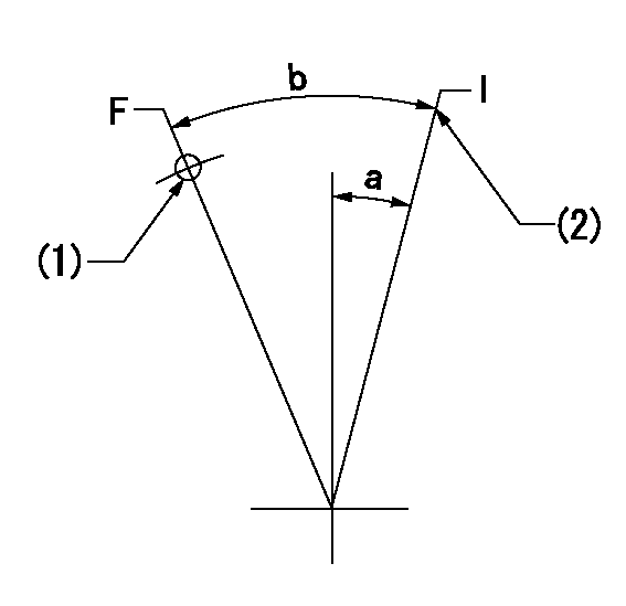
F:Full speed
I:Idle
(1)Use the hole at R = aa
(2)Stopper bolt set position 'H'
----------
aa=35mm
----------
a=14deg+-5deg b=40deg+-3deg
----------
aa=35mm
----------
a=14deg+-5deg b=40deg+-3deg
Stop lever angle
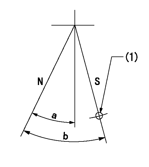
N:Pump normal
S:Stop the pump.
(1)Use the hole at R = aa
----------
aa=46.5mm
----------
a=34.5deg+-5deg b=40deg+-5deg
----------
aa=46.5mm
----------
a=34.5deg+-5deg b=40deg+-5deg
0000001501 I/P WITH LOAD PLUNGER ADJ
Plunger assembly number: PL (stamping: ST)
1. Adjustment procedures
(1)Insert the pre-stroke adjusting shims L1 for each cylinder.
(2)Adjust injection quantity.(max. var. bet. cyl. idling a1, full a2)
(3)At basic point A, adjust so that the pre-stroke is L2.
(4)Reconfirm the injection quantity.
----------
PL=131153-9020 ST=A769 L1=1mm L2=4.7+-0.05mm a1=+-14% a2=+-2.5%
----------
----------
PL=131153-9020 ST=A769 L1=1mm L2=4.7+-0.05mm a1=+-14% a2=+-2.5%
----------
Timing setting

(1)Pump vertical direction
(2)Position of timer's threaded hole at No 1 cylinder's beginning of injection
(3)B.T.D.C.: aa
(4)At rack position = bb
----------
aa=6deg bb=R1(13)mm
----------
a=(150deg)
----------
aa=6deg bb=R1(13)mm
----------
a=(150deg)
Information:
Make reference to ANALYZING TURBOCHARGER FAILURE, Form No. FEG45138.(1) See TURBOCHARGER IMPELLER INSTALLATION. Do not bend or add stress to the shaft when nut is tightened.(2) Torque for bolts holding thrust plate ... 40 5 lb. in.(4.5 0.6 N m)(3) Tighten bolt holding band clamp to ... 120 10 lb. in.(13.6 1.1 N m)(4) Put 5P3931 Anti-Seize Compound on threads of bolts holding turbine housing and tighten to ... 175 15 lb. in.(19.8 1.7 N m)(5) Put 5P3931 Anti-Seize Compound on threads of bolts holding turbocharger to manifold and tighten to ... 40 4 lb. ft.(55 5 N m)(6) End play for shaft (new) ... .006 to .011 in.(0.15 to 0.27 mm)(7) Bore in the bearing ... .6268 to .6272 in.(15.921 to 15.931 mm) Diameter of surface on shaft (journal) for the bearing ... .6250 to .6254 in.(15.875 to 15.885 mm)(8) Bore in housing ... .9827 to .9832 in.(24.961 to 24.973 mm) Outside diameter of the bearing ... .9780 to .9785 in.(24.841 to 24.854 mm)(9) Clearance between ends of oil seal ring ... .008 to .015 in.(0.20 to 0.38 mm) The radial clearance for the shaft is .004 to .009 in. (0.10 to 0.23 mm).(AiResearch TV81)
(1) Nut for impeller (See TURBOCHARGER IMPELLER INSTALLATION). Do not bend or add stress to the shaft when nut is tightened.(2) Torque for the bolts that hold the backplate ... 90 10 lb. in.(10.2 1.1 N m)(3) Torque for the clamp bolts ... 10 1 lb. ft.(14 1 N m)(4) Bore in the bearings ... .6268 to .6272 in.(15.921 to 15.931 mm) Diameter for the surfaces (journals) on the shaft for the bearings ... .6250 to .6254 in.(15.875 to 15.885 mm)(5) Bore in the housing ... .9827 to .9832 in.(24.961 to 24.973 mm) Outside diameter of the bearings ... .9782 to .9787 in.(24.846 to 24.859 mm)(6) Clearance between the ends of the oil seal ring ... .008 to .015 in.(0.20 to 0.38 mm)(7) End play for the shaft ... .003 to .010 in.(0.08 to 0.25 mm)(8) Torque for support nuts (put 5P3931 Anti-Seize Compound on the stud threads) ... 40 4 lb. ft.(55 5 N m)(AiResearch T18)
Make reference to ANALYZING TURBOCHARGER FAILURE, Form No. FEG45138.(1) End play for shaft ... .0065 .0025 in.(0.165 0.063 mm) Radial clearance for the shaft ... .004 to .009 in.(0.10 to 0.23 mm)(2) Bore in the bearing ... .6268 to .6272 in.(15.921 to 15.931 mm) Diameter of surface on shaft (journal) for the bearing ... .6250 to .6254 in.(15.875 to 15.885 mm)(3) Put 8S6747 Gasket Sealer on bolts holding compressor housing and tighten to ... 105 5 lb. in.(11.9 0.6 N m)(4) Put 5P3931 Anti-Seize Compound on bolts holding turbine housing and tighten to ... 175 15 lb. in.(19.8 1.7 N m)(5) Put 5P3931 Anti-Seize Compound on threads of bolts that hold turbocharger to manifold and tighten to ... 40 4 lb. ft.(55 5 N