Information injection-pump assembly
BOSCH
F 01G 09U 049
f01g09u049
ZEXEL
101603-8483
1016038483
ISUZU
8943957503
8943957503
Rating:
Service parts 101603-8483 INJECTION-PUMP ASSEMBLY:
1.
_

7.
COUPLING PLATE
8.
_
9.
_
11.
Nozzle and Holder
8-94393-335-1
12.
Open Pre:MPa(Kqf/cm2)
16.2{165}/18.1{185}
15.
NOZZLE SET
Include in #1:
101603-8483
as INJECTION-PUMP ASSEMBLY
Include in #2:
104741-5382
as _
Cross reference number
BOSCH
F 01G 09U 049
f01g09u049
ZEXEL
101603-8483
1016038483
ISUZU
8943957503
8943957503
Zexel num
Bosch num
Firm num
Name
101603-8483
F 01G 09U 049
8943957503 ISUZU
INJECTION-PUMP ASSEMBLY
6HH1-S * K 14BF PE6AD PE
6HH1-S * K 14BF PE6AD PE
Calibration Data:
Adjustment conditions
Test oil
1404 Test oil ISO4113 or {SAEJ967d}
1404 Test oil ISO4113 or {SAEJ967d}
Test oil temperature
degC
40
40
45
Nozzle and nozzle holder
105780-8140
Bosch type code
EF8511/9A
Nozzle
105780-0000
Bosch type code
DN12SD12T
Nozzle holder
105780-2080
Bosch type code
EF8511/9
Opening pressure
MPa
17.2
Opening pressure
kgf/cm2
175
Injection pipe
Outer diameter - inner diameter - length (mm) mm 6-2-600
Outer diameter - inner diameter - length (mm) mm 6-2-600
Overflow valve
131424-4920
Overflow valve opening pressure
kPa
127
107
147
Overflow valve opening pressure
kgf/cm2
1.3
1.1
1.5
Tester oil delivery pressure
kPa
157
157
157
Tester oil delivery pressure
kgf/cm2
1.6
1.6
1.6
Direction of rotation (viewed from drive side)
Left L
Left L
Injection timing adjustment
Direction of rotation (viewed from drive side)
Left L
Left L
Injection order
1-5-3-6-
2-4
Pre-stroke
mm
4.7
4.65
4.75
Rack position
After adjusting injection quantity. R=A
After adjusting injection quantity. R=A
Beginning of injection position
Governor side NO.1
Governor side NO.1
Difference between angles 1
Cal 1-5 deg. 60 59.5 60.5
Cal 1-5 deg. 60 59.5 60.5
Difference between angles 2
Cal 1-3 deg. 120 119.5 120.5
Cal 1-3 deg. 120 119.5 120.5
Difference between angles 3
Cal 1-6 deg. 180 179.5 180.5
Cal 1-6 deg. 180 179.5 180.5
Difference between angles 4
Cyl.1-2 deg. 240 239.5 240.5
Cyl.1-2 deg. 240 239.5 240.5
Difference between angles 5
Cal 1-4 deg. 300 299.5 300.5
Cal 1-4 deg. 300 299.5 300.5
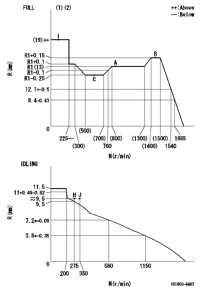
Injection quantity adjustment
Adjusting point
-
Rack position
13
Pump speed
r/min
850
850
850
Average injection quantity
mm3/st.
86.5
84.9
88.1
Max. variation between cylinders
%
0
-2.5
2.5
Basic
*
Fixing the rack
*
Standard for adjustment of the maximum variation between cylinders
*
Injection quantity adjustment_02
Adjusting point
-
Rack position
9.6+-0.5
Pump speed
r/min
275
275
275
Average injection quantity
mm3/st.
9.4
8.1
10.7
Max. variation between cylinders
%
0
-14
14
Fixing the rack
*
Standard for adjustment of the maximum variation between cylinders
*
Remarks
Adjust only variation between cylinders; adjust governor according to governor specifications.
Adjust only variation between cylinders; adjust governor according to governor specifications.
Injection quantity adjustment_03
Adjusting point
A
Rack position
R1(13)
Pump speed
r/min
850
850
850
Average injection quantity
mm3/st.
86.5
85.5
87.5
Basic
*
Fixing the lever
*
Injection quantity adjustment_04
Adjusting point
B
Rack position
R1+0.15
Pump speed
r/min
1450
1450
1450
Average injection quantity
mm3/st.
95.5
92.3
98.7
Fixing the lever
*
Injection quantity adjustment_05
Adjusting point
C
Rack position
R1-0.25
Pump speed
r/min
600
600
600
Average injection quantity
mm3/st.
77.5
74.3
80.7
Fixing the lever
*
Timer adjustment
Pump speed
r/min
905--
Advance angle
deg.
0
0
0
Load
3/5
Remarks
Start
Start
Timer adjustment_02
Pump speed
r/min
855
Advance angle
deg.
0.3
Load
3/5
Timer adjustment_03
Pump speed
r/min
-
Advance angle
deg.
1.5
1
2
Load
5/5
Remarks
Measure the actual speed.
Measure the actual speed.
Timer adjustment_04
Pump speed
r/min
1110
Advance angle
deg.
1.5
1
2
Load
3/5
Timer adjustment_05
Pump speed
r/min
1450
Advance angle
deg.
7
6.5
7.5
Load
5/5
Remarks
Finish
Finish
Test data Ex:
Governor adjustment
N:Pump speed
R:Rack position (mm)
(1)Torque cam stamping: T1
(2)Tolerance for racks not indicated: +-0.05mm.
----------
T1=K09
----------
----------
T1=K09
----------
Speed control lever angle
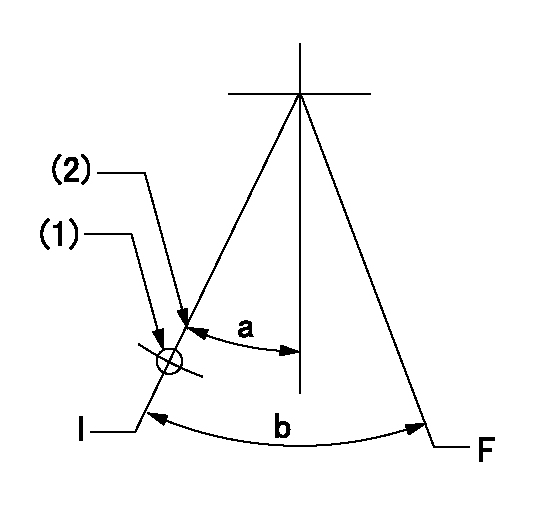
F:Full speed
I:Idle
(1)Use the hole at R = aa
(2)Stopper bolt set position 'H'
----------
aa=60mm
----------
a=28.5deg+-5deg b=40deg+-3deg
----------
aa=60mm
----------
a=28.5deg+-5deg b=40deg+-3deg
Stop lever angle
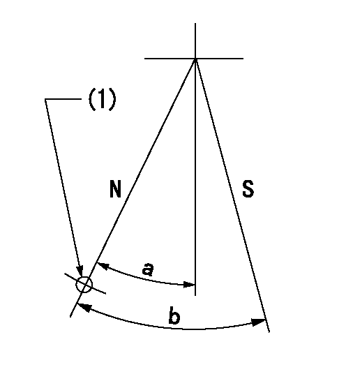
N:Pump normal
S:Stop the pump.
(1)Use the pin at R = aa
----------
aa=46.5mm
----------
a=34.5deg+-5deg b=40deg+-5deg
----------
aa=46.5mm
----------
a=34.5deg+-5deg b=40deg+-5deg
0000001501 I/P WITH LOAD PLUNGER ADJ
Plunger assembly number: PL (stamping: ST)
1. Adjustment procedures
(1)Insert the pre-stroke adjusting shims L1 for each cylinder.
(2)Adjust injection quantity.(max. var. bet. cyl. idling a1, full a2)
(3)At basic point A, adjust so that the pre-stroke is L2.
(4)Reconfirm the injection quantity.
----------
PL=131153-9020 ST=A769 L1=1mm L2=4.7+-0.05mm a1=+-14% a2=+-2.5%
----------
----------
PL=131153-9020 ST=A769 L1=1mm L2=4.7+-0.05mm a1=+-14% a2=+-2.5%
----------
0000001601 AIR CYLINDER

1. (1) Set the speed lever to idle.
(2)Screw in air cylinder (A)
(3)Set the clearance from the speed lever (B) at approximately L.
----------
L=1mm
----------
----------
L=1mm
----------
Timing setting

(1)Pump vertical direction
(2)Position of timer's threaded hole at No 1 cylinder's beginning of injection
(3)B.T.D.C.: aa
(4)At rack position = bb
----------
aa=6deg bb=R1(13)mm
----------
a=(150deg)
----------
aa=6deg bb=R1(13)mm
----------
a=(150deg)
Information:
GUIDELINES FOR REUSABLE PARTS; VALVES AND VALVE SPRINGS, Form SEBF8002, has the procedure necessary for checking used valves and valve springs.(1) 4N5906 Spring for valves (new): Length under test force ... 2.165 in.(54.9 mm)Test force ... 77.0 7.6 lb.(344 34 N)Use again minimum load at length under test force ... 65.4 lb.(291 N)Length of spring at valve open position ... 1.690 in.(42.93 mm)Use again minimum load at valve open position ... 183.6 lb.(817 N)Free length after test ... 2.47 in.(62.7 mm)Outside diameter ... 1.250 in.(31.75 mm)Spring must not be bent more than ... .086 in.(2.18 mm)(2) Height to top of valve guide ... 1.27 .03 in.(32.3 0.8 mm)(3) Diameter of valve stem (new) ... .3717 .0003 in.(9.441 0.008 mm) Use again minimum:4N5653 Exhaust ... Do Not Use Again4N5654 Intake ... .3704 in.(9.408 mm)Bore in valve guide with guide installed in the head (new) ... .3735 .0010 in.(9.487 0.025 mm)(4) Diameter of valve head: Exhaust valve ... 1.646 .005 in.(41.81 0.13 mm)Intake valve ... 1.771 .005 in.(44.98 0.13 mm)(5) Angle of intake valve face ... 291/4° 1/4°Angle of exhaust valve face ... 441/4° 1/4° (6) Depth of bore in head for valve seat insert ... .512 .015 in.(13.00 0.38 mm)(7) Diameter of valve seat insert for exhaust valve ... 1.6870 .0005 in.(42.850 0.013 mm) Bore in head for valve seat insert for exhaust valve ... 1.684 .001 in.(42.77 0.03 mm)Diameter of valve seat insert for intake valve ... 1.8120 .0005 in.(46.025 0.013 mm)Bore in head for valve seat insert for intake valve ... 1.809 .001 in.(45.95 0.03 mm)(8) Angle of face of intake valve seat insert ... 301/4° 1/2°Angle of face of exhaust valve seat insert ... 451/4° 1/2°(9) Dimension from top of closed valve to face of head: Maximum permissible dimension for intake and exhaust ... .048 in.(1.22 mm)Minimum permissible dimension for intake and exhaust ... .008 in.(0.20 mm)(10) Outside diameter of the face of the valve seat insert: Exhaust seat ... 1.591 .005 in.(40.41 0.13 mm)Intake seat ... 1.734 .005 in.(44.04 0.13 mm)(11) "Use again" thickness of valve lip: Exhaust valve ... .080 in.(2.03 mm)Intake valve ... .099 in.(2.51 mm)
Have questions with 101603-8483?
Group cross 101603-8483 ZEXEL
Isuzu
101603-8483
F 01G 09U 049
8943957503
INJECTION-PUMP ASSEMBLY
6HH1-S
6HH1-S