Information injection-pump assembly
ZEXEL
101603-8423
1016038423
ISUZU
8943901640
8943901640
Rating:
Service parts 101603-8423 INJECTION-PUMP ASSEMBLY:
1.
_

7.
COUPLING PLATE
8.
_
9.
_
11.
Nozzle and Holder
8-94393-335-1
12.
Open Pre:MPa(Kqf/cm2)
16.2{165}/18.1{185}

15.
NOZZLE SET
Cross reference number
ZEXEL
101603-8423
1016038423
ISUZU
8943901640
8943901640
Zexel num
Bosch num
Firm num
Name
Calibration Data:
Adjustment conditions
Test oil
1404 Test oil ISO4113 or {SAEJ967d}
1404 Test oil ISO4113 or {SAEJ967d}
Test oil temperature
degC
40
40
45
Nozzle and nozzle holder
105780-8140
Bosch type code
EF8511/9A
Nozzle
105780-0000
Bosch type code
DN12SD12T
Nozzle holder
105780-2080
Bosch type code
EF8511/9
Opening pressure
MPa
17.2
Opening pressure
kgf/cm2
175
Injection pipe
Outer diameter - inner diameter - length (mm) mm 6-2-600
Outer diameter - inner diameter - length (mm) mm 6-2-600
Overflow valve
131424-4920
Overflow valve opening pressure
kPa
127
107
147
Overflow valve opening pressure
kgf/cm2
1.3
1.1
1.5
Tester oil delivery pressure
kPa
157
157
157
Tester oil delivery pressure
kgf/cm2
1.6
1.6
1.6
Direction of rotation (viewed from drive side)
Left L
Left L
Injection timing adjustment
Direction of rotation (viewed from drive side)
Left L
Left L
Injection order
1-5-3-6-
2-4
Pre-stroke
mm
4.7
4.65
4.75
Rack position
After adjusting injection quantity. R=A
After adjusting injection quantity. R=A
Beginning of injection position
Governor side NO.1
Governor side NO.1
Difference between angles 1
Cal 1-5 deg. 60 59.5 60.5
Cal 1-5 deg. 60 59.5 60.5
Difference between angles 2
Cal 1-3 deg. 120 119.5 120.5
Cal 1-3 deg. 120 119.5 120.5
Difference between angles 3
Cal 1-6 deg. 180 179.5 180.5
Cal 1-6 deg. 180 179.5 180.5
Difference between angles 4
Cyl.1-2 deg. 240 239.5 240.5
Cyl.1-2 deg. 240 239.5 240.5
Difference between angles 5
Cal 1-4 deg. 300 299.5 300.5
Cal 1-4 deg. 300 299.5 300.5
Injection quantity adjustment
Adjusting point
-
Rack position
12.3
Pump speed
r/min
850
850
850
Average injection quantity
mm3/st.
87
85.4
88.6
Max. variation between cylinders
%
0
-2.5
2.5
Basic
*
Fixing the rack
*
Standard for adjustment of the maximum variation between cylinders
*
Injection quantity adjustment_02
Adjusting point
H
Rack position
9.5+-0.5
Pump speed
r/min
275
275
275
Average injection quantity
mm3/st.
8
6.7
9.3
Max. variation between cylinders
%
0
-14
14
Fixing the rack
*
Standard for adjustment of the maximum variation between cylinders
*
Injection quantity adjustment_03
Adjusting point
A
Rack position
R1(12.3)
Pump speed
r/min
850
850
850
Average injection quantity
mm3/st.
87
86
88
Basic
*
Fixing the lever
*
Injection quantity adjustment_04
Adjusting point
B
Rack position
(R1+0.1)
Pump speed
r/min
1425
1425
1425
Average injection quantity
mm3/st.
98
94.8
101.2
Fixing the lever
*
Injection quantity adjustment_05
Adjusting point
C
Rack position
R1-0.15
Pump speed
r/min
600
600
600
Average injection quantity
mm3/st.
75
71.8
78.2
Fixing the lever
*
Timer adjustment
Pump speed
r/min
905--
Advance angle
deg.
0
0
0
Load
3/5
Remarks
Start
Start
Timer adjustment_02
Pump speed
r/min
855
Advance angle
deg.
0.3
Load
3/5
Timer adjustment_03
Pump speed
r/min
-
Advance angle
deg.
1.5
1
2
Load
5/5
Remarks
Measure the actual speed.
Measure the actual speed.
Timer adjustment_04
Pump speed
r/min
1110
Advance angle
deg.
1.5
1
2
Load
3/5
Timer adjustment_05
Pump speed
r/min
1450
Advance angle
deg.
7
6.5
7.5
Load
5/5
Remarks
Finish
Finish
Test data Ex:
Governor adjustment
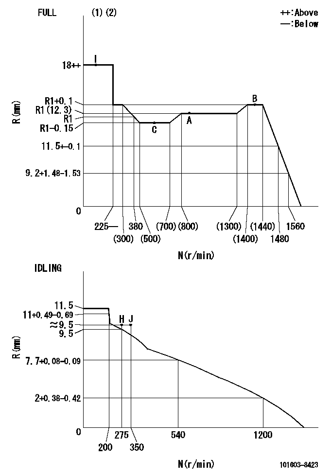
N:Pump speed
R:Rack position (mm)
(1)Torque cam stamping: T1
(2)Tolerance for racks not indicated: +-0.05mm.
----------
T1=L49
----------
----------
T1=L49
----------
Speed control lever angle

F:Full speed
I:Idle
(1)Use the hole at R = aa
(2)Stopper bolt set position 'H'
----------
aa=39.5mm
----------
a=11deg+-5deg b=43deg+-3deg
----------
aa=39.5mm
----------
a=11deg+-5deg b=43deg+-3deg
Stop lever angle

N:Pump normal
S:Stop the pump.
(1)Use the pin at R = aa
----------
aa=45mm
----------
a=12.5deg+-5deg b=40deg+-5deg
----------
aa=45mm
----------
a=12.5deg+-5deg b=40deg+-5deg
0000001501 I/P WITH LOAD PLUNGER ADJ
Plunger assembly number: PL (stamping: ST)
1. Adjustment procedures
(1)Insert the pre-stroke adjusting shims L1 for each cylinder.
(2)Adjust injection quantity.(max. var. bet. cyl. idling a1, full a2)
(3)At basic point A, adjust so that the pre-stroke is L2.
(4)Reconfirm the injection quantity.
----------
PL=131150-0420 ST=A792 L1=1mm L2=4.7+-0.05mm a1=+-14% a2=+-2.5%
----------
----------
PL=131150-0420 ST=A792 L1=1mm L2=4.7+-0.05mm a1=+-14% a2=+-2.5%
----------
Timing setting

(1)Pump vertical direction
(2)Position of timer's threaded hole at No 1 cylinder's beginning of injection
(3)B.T.D.C.: aa
(4)At rack position = bb
----------
aa=6deg bb=R1(12.3)mm
----------
a=(150deg)
----------
aa=6deg bb=R1(12.3)mm
----------
a=(150deg)
Information:
1. Remove all of bolts (1) and bolts (2) and (3).2. Use two 3/8"-16 NC forcing screws and remove stator (4) from the flywheel housing. 3. If necessary remove the lip type seal from stator (4) with a hammer and punch. 4. Remove the six O-ring seals (6) from the flywheel housing.5. Remove rotor (5) from the crankshaft. 6. Remove the seal ring from carrier (8).7. If necessary remove carrier (8) and sleeve (7) from rotor (5). The carrier and sleeve will have damage after removal. Use new parts for replacement.Install BrakeSaver
1. If the carrier and sleeve were removed from the rotor, heat the new parts to a maximum temperature of 300° F (149° C). 2. Install carrier (2) on rotor (3).3. Put 7M7260 Liquid Gasket Material on the outside diameter (4) of rotor (3) and let it dry. Install sleeve (1) on rotor (3) as shown. 4. Install seal ring (5) in the carrier. 5. Install two 3/4"-16 NF guide bolts (6) a minimum of 5 in. long in the crankshaft.6. Make sure the O-ring seal is on rear face of the crankshaft seal carrier and install rotor (3) on the guide bolts with the marked bolt hole of the rotor in alignment with the marked hole of the crankshaft. 7. Use tool (A) and a press to install the seal in stator (7) as shown. 8. Install O-ring seal in position on stator (7). Install O-ring seals (8) in the flywheel housing.9. Put stator (7) in position on the flywheel housing. 10. Put 9S3263 Thread Lock on the threads of the bolts that hold the stator and install them. Tighten all of bolts (9) evenly to a torque of 40 5 lb. ft. (55 7 N m). Tighten bolts (10) and (11) to a torque of 90 10 lb. ft. (120 14 N m).end by: a) install flywheel
1. If the carrier and sleeve were removed from the rotor, heat the new parts to a maximum temperature of 300° F (149° C). 2. Install carrier (2) on rotor (3).3. Put 7M7260 Liquid Gasket Material on the outside diameter (4) of rotor (3) and let it dry. Install sleeve (1) on rotor (3) as shown. 4. Install seal ring (5) in the carrier. 5. Install two 3/4"-16 NF guide bolts (6) a minimum of 5 in. long in the crankshaft.6. Make sure the O-ring seal is on rear face of the crankshaft seal carrier and install rotor (3) on the guide bolts with the marked bolt hole of the rotor in alignment with the marked hole of the crankshaft. 7. Use tool (A) and a press to install the seal in stator (7) as shown. 8. Install O-ring seal in position on stator (7). Install O-ring seals (8) in the flywheel housing.9. Put stator (7) in position on the flywheel housing. 10. Put 9S3263 Thread Lock on the threads of the bolts that hold the stator and install them. Tighten all of bolts (9) evenly to a torque of 40 5 lb. ft. (55 7 N m). Tighten bolts (10) and (11) to a torque of 90 10 lb. ft. (120 14 N m).end by: a) install flywheel