Information injection-pump assembly
ZEXEL
101603-8420
1016038420
ISUZU
8943955220
8943955220

Rating:
Cross reference number
ZEXEL
101603-8420
1016038420
ISUZU
8943955220
8943955220
Zexel num
Bosch num
Firm num
Name
Calibration Data:
Adjustment conditions
Test oil
1404 Test oil ISO4113 or {SAEJ967d}
1404 Test oil ISO4113 or {SAEJ967d}
Test oil temperature
degC
40
40
45
Nozzle and nozzle holder
105780-8140
Bosch type code
EF8511/9A
Nozzle
105780-0000
Bosch type code
DN12SD12T
Nozzle holder
105780-2080
Bosch type code
EF8511/9
Opening pressure
MPa
17.2
Opening pressure
kgf/cm2
175
Injection pipe
Outer diameter - inner diameter - length (mm) mm 6-2-600
Outer diameter - inner diameter - length (mm) mm 6-2-600
Overflow valve
131424-4920
Overflow valve opening pressure
kPa
127
107
147
Overflow valve opening pressure
kgf/cm2
1.3
1.1
1.5
Tester oil delivery pressure
kPa
157
157
157
Tester oil delivery pressure
kgf/cm2
1.6
1.6
1.6
Direction of rotation (viewed from drive side)
Left L
Left L
Injection timing adjustment
Direction of rotation (viewed from drive side)
Left L
Left L
Injection order
1-5-3-6-
2-4
Pre-stroke
mm
4.7
4.65
4.75
Rack position
After adjusting injection quantity. R=A
After adjusting injection quantity. R=A
Beginning of injection position
Governor side NO.1
Governor side NO.1
Difference between angles 1
Cal 1-5 deg. 60 59.5 60.5
Cal 1-5 deg. 60 59.5 60.5
Difference between angles 2
Cal 1-3 deg. 120 119.5 120.5
Cal 1-3 deg. 120 119.5 120.5
Difference between angles 3
Cal 1-6 deg. 180 179.5 180.5
Cal 1-6 deg. 180 179.5 180.5
Difference between angles 4
Cyl.1-2 deg. 240 239.5 240.5
Cyl.1-2 deg. 240 239.5 240.5
Difference between angles 5
Cal 1-4 deg. 300 299.5 300.5
Cal 1-4 deg. 300 299.5 300.5
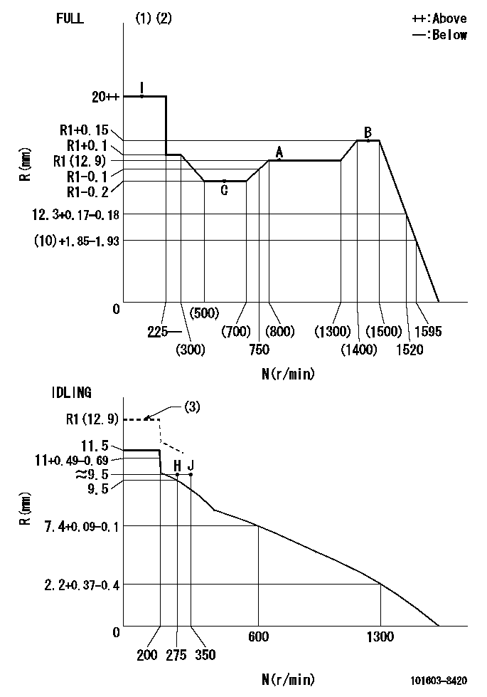
Injection quantity adjustment
Adjusting point
-
Rack position
12.9
Pump speed
r/min
850
850
850
Average injection quantity
mm3/st.
84
82.4
85.6
Max. variation between cylinders
%
0
-2.5
2.5
Basic
*
Fixing the rack
*
Standard for adjustment of the maximum variation between cylinders
*
Injection quantity adjustment_02
Adjusting point
-
Rack position
9.6+-0.5
Pump speed
r/min
275
275
275
Average injection quantity
mm3/st.
9.4
8.1
10.7
Max. variation between cylinders
%
0
-14
14
Fixing the rack
*
Standard for adjustment of the maximum variation between cylinders
*
Remarks
Adjust only variation between cylinders; adjust governor according to governor specifications.
Adjust only variation between cylinders; adjust governor according to governor specifications.
Injection quantity adjustment_03
Adjusting point
A
Rack position
R1(12.9)
Pump speed
r/min
850
850
850
Average injection quantity
mm3/st.
84
83
85
Basic
*
Fixing the lever
*
Injection quantity adjustment_04
Adjusting point
B
Rack position
R1+0.15
Pump speed
r/min
1450
1450
1450
Average injection quantity
mm3/st.
94.5
91.3
97.7
Fixing the lever
*
Injection quantity adjustment_05
Adjusting point
C
Rack position
R1-0.2
Pump speed
r/min
600
600
600
Average injection quantity
mm3/st.
75
71.8
78.2
Fixing the lever
*
Timer adjustment
Pump speed
r/min
905--
Advance angle
deg.
0
0
0
Load
3/5
Remarks
Start
Start
Timer adjustment_02
Pump speed
r/min
855
Advance angle
deg.
0.3
Load
3/5
Timer adjustment_03
Pump speed
r/min
-
Advance angle
deg.
1.5
1
2
Load
5/5
Remarks
Measure the actual speed.
Measure the actual speed.
Timer adjustment_04
Pump speed
r/min
1110
Advance angle
deg.
1.5
1
2
Load
3/5
Timer adjustment_05
Pump speed
r/min
1450
Advance angle
deg.
7
6.5
7.5
Load
5/5
Remarks
Finish
Finish
Test data Ex:
Governor adjustment
N:Pump speed
R:Rack position (mm)
(1)Torque cam stamping: T1
(2)Tolerance for racks not indicated: +-0.05mm.
(3)At delivery (at R = RA, N = N1)
----------
T1=J73 RA=R1(12.9)mm N1=150r/min
----------
----------
T1=J73 RA=R1(12.9)mm N1=150r/min
----------
Speed control lever angle
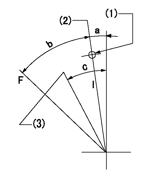
F:Full speed
I:Idle
(1)Use the hole at R = aa
(2)Stopper bolt set position 'H'
(3)Set the idle side stopper bolt at rack position = bb (at shipping).
----------
aa=43mm bb=R1(12.9)mm
----------
a=11deg+-5deg b=(45deg)+-3deg c=(14deg)
----------
aa=43mm bb=R1(12.9)mm
----------
a=11deg+-5deg b=(45deg)+-3deg c=(14deg)
Stop lever angle

N:Pump normal
S:Stop the pump.
(1)Use the pin at R = aa
----------
aa=45mm
----------
a=12.5deg+-5deg b=40deg+-5deg
----------
aa=45mm
----------
a=12.5deg+-5deg b=40deg+-5deg
0000001501 I/P WITH LOAD PLUNGER ADJ
Plunger assembly number: PL (stamping: ST)
1. Adjustment procedures
(1)Insert the pre-stroke adjusting shims L1 for each cylinder.
(2)Adjust injection quantity.(max. var. bet. cyl. idling a1, full a2)
(3)At basic point A, adjust so that the pre-stroke is L2.
(4)Reconfirm the injection quantity.
----------
PL=131153-9020 ST=A769 L1=1mm L2=4.7+-0.05mm a1=+-14% a2=+-2.5%
----------
----------
PL=131153-9020 ST=A769 L1=1mm L2=4.7+-0.05mm a1=+-14% a2=+-2.5%
----------
Timing setting

(1)Pump vertical direction
(2)Position of timer's threaded hole at No 1 cylinder's beginning of injection
(3)B.T.D.C.: aa
(4)-
----------
aa=6deg
----------
a=(150deg)
----------
aa=6deg
----------
a=(150deg)
Information:
3. Remove bearing caps (1) from the two connecting rods. Put pieces of rubber hose or tape on the threads of the connecting rod bolts as protection for the crankshaft. 4. Push the pistons up until the piston rings are clear of the cylinder liner. Remove pistons (2). Put identification on each piston as to its location for correct installation and alignment. Keep each cap with its connecting rod.
Do not turn the crankshaft while any of the connecting rods are in the engine without the caps installed.
5. Do Steps 1 through 4 for the remainder of the pistons.Install Pistons
1. Put clean engine oil on the piston rings, connecting rod bearings and cylinder liner. 2. Install piston into cylinder liner with tool (A). Push piston and rings through tool (A) with a hammer handle.3. Make a check of the connecting rod bearing clearance. See REMOVE AND INSTALL CONNECTING ROD BEARINGS. 4. Put clean engine oil on connecting rod cap and bearing. Install the cap (1) on the connecting rod. Tighten nuts to a torque of 50 5 lb. ft. (70 7 N m) plus 180°.5. Do Steps 1 through 4 for the remainder of the pistons.
As caps are installed, make sure that number identification on cap is on same side as number identification on rod.
end by: a) install cylinder head and spacer plateb) install oil pumpDisassemble Pistons
start by: a) remove pistons 1. Remove the retaining rings (2) for the piston pin.2. Remove piston pin (1) and remove piston from the connecting rod.3. Remove the piston rings using ring expander (A).Assemble Pistons
1. Use ring expander (A) to install the piston rings. The two compression rings have marks "UP-1" and "UP-2". The rings must be installed with the marks toward the top of the piston with "UP-1" being the top ring. Put the ring gaps in place 120° from each other.2. Put clean oil on the piston pin. Put the piston in place on the connecting rod. Install the piston pin and retaining rings. On some engines there can be a "V" mark (2) on the piston. This mark must be on the same side as the location number (1) on the connecting rod.end by: a) install pistons