Information injection-pump assembly
ZEXEL
101603-8401
1016038401
ISUZU
8943955721
8943955721

Rating:
Cross reference number
ZEXEL
101603-8401
1016038401
ISUZU
8943955721
8943955721
Zexel num
Bosch num
Firm num
Name
Calibration Data:
Adjustment conditions
Test oil
1404 Test oil ISO4113 or {SAEJ967d}
1404 Test oil ISO4113 or {SAEJ967d}
Test oil temperature
degC
40
40
45
Nozzle and nozzle holder
105780-8140
Bosch type code
EF8511/9A
Nozzle
105780-0000
Bosch type code
DN12SD12T
Nozzle holder
105780-2080
Bosch type code
EF8511/9
Opening pressure
MPa
17.2
Opening pressure
kgf/cm2
175
Injection pipe
Outer diameter - inner diameter - length (mm) mm 6-2-600
Outer diameter - inner diameter - length (mm) mm 6-2-600
Overflow valve
131424-4920
Overflow valve opening pressure
kPa
127
107
147
Overflow valve opening pressure
kgf/cm2
1.3
1.1
1.5
Tester oil delivery pressure
kPa
157
157
157
Tester oil delivery pressure
kgf/cm2
1.6
1.6
1.6
Direction of rotation (viewed from drive side)
Left L
Left L
Injection timing adjustment
Direction of rotation (viewed from drive side)
Left L
Left L
Injection order
1-5-3-6-
2-4
Pre-stroke
mm
4.7
4.65
4.75
Rack position
After adjusting injection quantity. R=A
After adjusting injection quantity. R=A
Beginning of injection position
Governor side NO.1
Governor side NO.1
Difference between angles 1
Cal 1-5 deg. 60 59.5 60.5
Cal 1-5 deg. 60 59.5 60.5
Difference between angles 2
Cal 1-3 deg. 120 119.5 120.5
Cal 1-3 deg. 120 119.5 120.5
Difference between angles 3
Cal 1-6 deg. 180 179.5 180.5
Cal 1-6 deg. 180 179.5 180.5
Difference between angles 4
Cyl.1-2 deg. 240 239.5 240.5
Cyl.1-2 deg. 240 239.5 240.5
Difference between angles 5
Cal 1-4 deg. 300 299.5 300.5
Cal 1-4 deg. 300 299.5 300.5
Injection quantity adjustment
Adjusting point
-
Rack position
13
Pump speed
r/min
850
850
850
Average injection quantity
mm3/st.
86.5
84.9
88.1
Max. variation between cylinders
%
0
-2.5
2.5
Basic
*
Fixing the rack
*
Standard for adjustment of the maximum variation between cylinders
*
Injection quantity adjustment_02
Adjusting point
-
Rack position
9.6+-0.5
Pump speed
r/min
275
275
275
Average injection quantity
mm3/st.
9.4
8.1
10.7
Max. variation between cylinders
%
0
-14
14
Fixing the rack
*
Standard for adjustment of the maximum variation between cylinders
*
Remarks
Adjust only variation between cylinders; adjust governor according to governor specifications.
Adjust only variation between cylinders; adjust governor according to governor specifications.
Injection quantity adjustment_03
Adjusting point
A
Rack position
R1(13)
Pump speed
r/min
850
850
850
Average injection quantity
mm3/st.
86.5
85.5
87.5
Basic
*
Fixing the lever
*
Injection quantity adjustment_04
Adjusting point
B
Rack position
R1+0.15
Pump speed
r/min
1450
1450
1450
Average injection quantity
mm3/st.
95.5
92.3
98.7
Fixing the lever
*
Injection quantity adjustment_05
Adjusting point
C
Rack position
R1-0.25
Pump speed
r/min
600
600
600
Average injection quantity
mm3/st.
77.5
74.3
80.7
Fixing the lever
*
Timer adjustment
Pump speed
r/min
905--
Advance angle
deg.
0
0
0
Load
3/5
Remarks
Start
Start
Timer adjustment_02
Pump speed
r/min
855
Advance angle
deg.
0.3
Load
3/5
Timer adjustment_03
Pump speed
r/min
1110
Advance angle
deg.
1.5
1
2
Load
3/5
Timer adjustment_04
Pump speed
r/min
-
Advance angle
deg.
1.5
1
2
Load
5/5
Remarks
Measure the actual speed.
Measure the actual speed.
Timer adjustment_05
Pump speed
r/min
1450
Advance angle
deg.
7
6.5
7.5
Load
5/5
Remarks
Finish
Finish
Test data Ex:
Governor adjustment
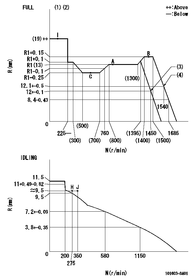
N:Pump speed
R:Rack position (mm)
(1)Torque cam stamping: T1
(2)Tolerance for racks not indicated: +-0.05mm.
(3)Air cylinder operating pressure: P1 or more
(4)Air cylinder operating pressure: P2
----------
T1=K09 P1=294kPa(3kgf/cm2) P2=0kPa(0kgf/cm2)
----------
----------
T1=K09 P1=294kPa(3kgf/cm2) P2=0kPa(0kgf/cm2)
----------
Speed control lever angle
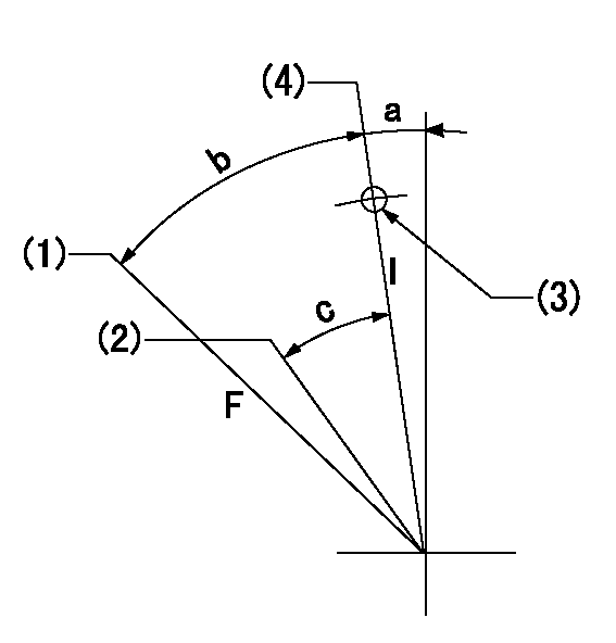
F:Full speed
I:Idle
(1)When air cylinder OFF.
(2)Air cylinder operating pressure: at P1
(3)Use the pin at R = aa
(4)Stopper bolt set position 'H'
----------
P1=294kPa(3kgf/cm2) aa=35mm
----------
a=10deg+-5deg b=40deg+-3deg c=(35deg)+-3deg
----------
P1=294kPa(3kgf/cm2) aa=35mm
----------
a=10deg+-5deg b=40deg+-3deg c=(35deg)+-3deg
Stop lever angle

N:Pump normal
S:Stop the pump.
(1)Use the pin at R = aa
----------
aa=45mm
----------
a=12.5deg+-5deg b=40deg+-5deg
----------
aa=45mm
----------
a=12.5deg+-5deg b=40deg+-5deg
0000001501 I/P WITH LOAD PLUNGER ADJ
Plunger assembly number: PL (stamping: ST)
1. Adjustment procedures
(1)Insert the pre-stroke adjusting shims L1 for each cylinder.
(2)Adjust injection quantity.(max. var. bet. cyl. idling a1, full a2)
(3)At basic point A, adjust so that the pre-stroke is L2.
(4)Reconfirm the injection quantity.
----------
PL=131153-9020 ST=A769 L1=1mm L2=4.7+-0.05mm a1=+-14% a2=+-2.5%
----------
----------
PL=131153-9020 ST=A769 L1=1mm L2=4.7+-0.05mm a1=+-14% a2=+-2.5%
----------
0000001601 AIR CYLINDER
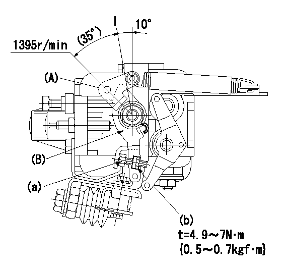
(A): Speed lever
(B): Speed lever
(a): Stopper bolt
(b): Nut
1. Air cylinder adjustment procedure
(1)Apply positive pressure P1 (ON) to the air cylinder.
(2)Operate the speed lever (A). (At this time speed lever (B) also moves together.)
(3)At speed N1 and rack position Ra, adjust using stopper bolt (b) so that speed lever (B) is at the stop position and speed lever (A) is in the cancel position.
(4)Confirm that the speed lever turns to the full position at positive pressure (OFF) P2.
(5)After repeating the above several times, fix the stopper bolt (a) using the nut (b).
----------
P1=294kPa(3kgf/cm2) P2=0kPa(0kgf/cm2) N1=1450r/min Ra=12+-0.1mm
----------
----------
P1=294kPa(3kgf/cm2) P2=0kPa(0kgf/cm2) N1=1450r/min Ra=12+-0.1mm
----------
Timing setting

(1)Pump vertical direction
(2)Position of timer's threaded hole at No 1 cylinder's beginning of injection
(3)B.T.D.C.: aa
(4)-
----------
aa=6deg
----------
a=(150deg)
----------
aa=6deg
----------
a=(150deg)
Information:
1. Remove the fuel ratio control, fuel shutoff solenoid, and idle screw housing from the governor housing (1). 2. Remove screw (2) that holds rack stop collar on.3. Remove rack stop collar (5), collar (3) and spring (4).4. Remove the bolts that hold governor housing to fuel injection pump housing.5. Remove the governor housing. 6. Remove seat assembly (8), governor spring (6) and washer type spring (7).7. Remove three bolts (11) and lock (9) that hold cylinder and weight assembly (10) to fuel injection pump housing.8. Pull the cylinder and weight assembly off the location dowels. 9. Move cylinder and weight assembly to the side to remove piston from rack (12).Connection Of Governor To Fuel Injection Pump Housing
1. Connect cylinder and weight assembly (1) to rack (2). 2. Push cylinder and weight assembly on to location dowels of pump housing and install bolts (3) and lock.3. Install the spring type washer on bolt (4) so the inside diameter of spring will make contact with the guide in governor housing (6). Install governor spring (7), washer type spring (8) and collar (5).4. Put governor housing (6) in place on the pump housing and install the bolts. 5. Install spring (12), collar (11) and rack stop collar (9).6. Install screw (10) in rack stop collar. 7. Install the idle screw housing, shutoff solenoid and fuel ratio control on the governor housing.8. Make an adjustment to the governor. See RACK SETTING AND GOVERNOR ADJUSTMENTS in TESTING AND ADJUSTING.end by:a) install fuel injection pump housing and governorDisassemble Governor
start by:a) separation of governor from fuel injection pump housing 1. Remove seat retaining ring (1) and pin (2). 2. Remove seat (3), bolt (4), washers (5) and spring (6).3. Remove the sleeve and bearing assembly from the cylinder and weight assemblies. 4. Remove retaining ring (7) from sleeve (8).5. Remove bearing (9) and races (10) from sleeve (8). 6. Remove valve (11) from piston (12).7. Remove the retaining ring (13) from the weight assembly (14).8. Remove weight assembly (14).9. Remove piston (12) and sleeve (15) from cylinder (16).10. Remove the O-ring seal from sleeve (15). 11. Remove speed limiter plug (17), spring (18) and plunger (19) from the governor housing.12. Remove high idle screw (21) and low idle screw (20). 13. Remove the bolt (22) and lock from the lever (24).14. Remove shaft (23) and lever (24) from governor housing.15. Remove the seal from the housing.16. Remove two bearings from the housing. Assemble Governor
1. Install detent plunger, spring and pin in levers.2. Install bearings in each side of the governor housing with tooling (A).3. Install levers and shaft in governor housing. The position of the bearings can make a difference in the position of the levers. With the levers pushed against the bearings on the boss side, clearance (X) between the guide for the governor spring and levers must be approximately .135 in. (3.43 mm). With levers pushed against other side the clearance (Y) on the other side must be approximately .100 in. (2.54