Information injection-pump assembly
ZEXEL
101603-8031
1016038031
ISUZU
8943937152
8943937152

Rating:
Cross reference number
ZEXEL
101603-8031
1016038031
ISUZU
8943937152
8943937152
Zexel num
Bosch num
Firm num
Name
Calibration Data:
Adjustment conditions
Test oil
1404 Test oil ISO4113 or {SAEJ967d}
1404 Test oil ISO4113 or {SAEJ967d}
Test oil temperature
degC
40
40
45
Nozzle and nozzle holder
105780-8140
Bosch type code
EF8511/9A
Nozzle
105780-0000
Bosch type code
DN12SD12T
Nozzle holder
105780-2080
Bosch type code
EF8511/9
Opening pressure
MPa
17.2
Opening pressure
kgf/cm2
175
Injection pipe
Outer diameter - inner diameter - length (mm) mm 6-2-600
Outer diameter - inner diameter - length (mm) mm 6-2-600
Overflow valve
131424-4920
Overflow valve opening pressure
kPa
127
107
147
Overflow valve opening pressure
kgf/cm2
1.3
1.1
1.5
Tester oil delivery pressure
kPa
157
157
157
Tester oil delivery pressure
kgf/cm2
1.6
1.6
1.6
Direction of rotation (viewed from drive side)
Left L
Left L
Injection timing adjustment
Direction of rotation (viewed from drive side)
Left L
Left L
Injection order
1-5-3-6-
2-4
Pre-stroke
mm
3.6
3.55
3.65
Beginning of injection position
Governor side NO.1
Governor side NO.1
Difference between angles 1
Cal 1-5 deg. 60 59.5 60.5
Cal 1-5 deg. 60 59.5 60.5
Difference between angles 2
Cal 1-3 deg. 120 119.5 120.5
Cal 1-3 deg. 120 119.5 120.5
Difference between angles 3
Cal 1-6 deg. 180 179.5 180.5
Cal 1-6 deg. 180 179.5 180.5
Difference between angles 4
Cyl.1-2 deg. 240 239.5 240.5
Cyl.1-2 deg. 240 239.5 240.5
Difference between angles 5
Cal 1-4 deg. 300 299.5 300.5
Cal 1-4 deg. 300 299.5 300.5
Injection quantity adjustment
Adjusting point
-
Rack position
11.5
Pump speed
r/min
900
900
900
Average injection quantity
mm3/st.
77.7
76.1
79.3
Max. variation between cylinders
%
0
-2.5
2.5
Basic
*
Fixing the rack
*
Standard for adjustment of the maximum variation between cylinders
*
Injection quantity adjustment_02
Adjusting point
H
Rack position
9.5+-0.5
Pump speed
r/min
265
265
265
Average injection quantity
mm3/st.
8.8
7.5
10.1
Max. variation between cylinders
%
0
-14
14
Fixing the rack
*
Standard for adjustment of the maximum variation between cylinders
*
Injection quantity adjustment_03
Adjusting point
A
Rack position
R1(11.5)
Pump speed
r/min
900
900
900
Average injection quantity
mm3/st.
77.7
76.7
78.7
Basic
*
Fixing the lever
*
Injection quantity adjustment_04
Adjusting point
B
Rack position
R1+0.3
Pump speed
r/min
1500
1500
1500
Average injection quantity
mm3/st.
93.3
89.3
97.3
Fixing the lever
*
Injection quantity adjustment_05
Adjusting point
C
Rack position
R1-0.25
Pump speed
r/min
600
600
600
Average injection quantity
mm3/st.
60.9
57.7
64.1
Fixing the lever
*
Injection quantity adjustment_06
Adjusting point
I
Rack position
-
Pump speed
r/min
150
150
150
Average injection quantity
mm3/st.
96
96
104
Fixing the lever
*
Timer adjustment
Pump speed
r/min
1300--
Advance angle
deg.
0
0
0
Remarks
Start
Start
Timer adjustment_02
Pump speed
r/min
1250
Advance angle
deg.
0.5
Timer adjustment_03
Pump speed
r/min
1500
Advance angle
deg.
4
3.5
4.5
Remarks
Finish
Finish
Test data Ex:
Governor adjustment
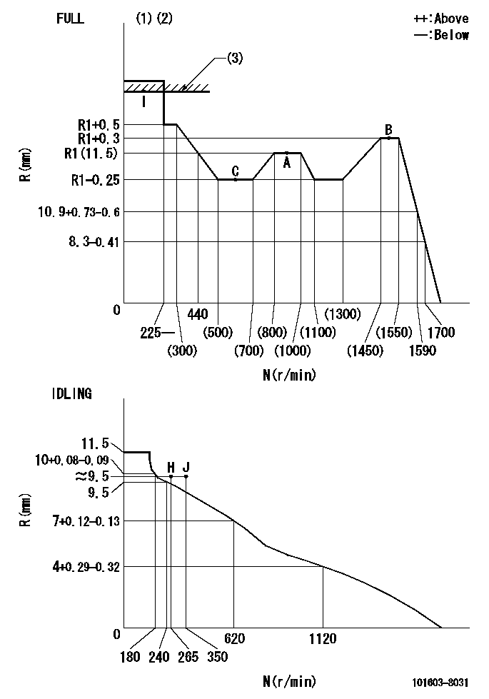
N:Pump speed
R:Rack position (mm)
(1)Torque cam stamping: T1
(2)Tolerance for racks not indicated: +-0.05mm.
(3)RACK LIMIT
----------
T1=H09
----------
----------
T1=H09
----------
Speed control lever angle
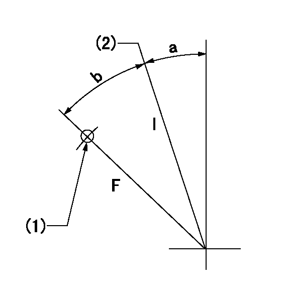
F:Full speed
I:Idle
(1)Use the pin at R = aa
(2)Stopper bolt set position 'H'
----------
aa=35mm
----------
a=11deg+-5deg b=36deg+-3deg
----------
aa=35mm
----------
a=11deg+-5deg b=36deg+-3deg
Stop lever angle

N:Pump normal
S:Stop the pump.
(1)Use the pin at R = aa
----------
aa=45mm
----------
a=12.5deg+-5deg b=40deg+-5deg
----------
aa=45mm
----------
a=12.5deg+-5deg b=40deg+-5deg
0000001501 ACS
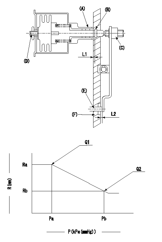
(A) Housing
(B) Snap ring
(C) adjusting screw
(D) Set screw
(E): Push rod
(F) Spacer
1. Adjustment of the aneroid compensator
(1)Adjust with the (D) set screw so that the clearance between the (A) housing and (B) snap ring is L1.
(2)Select the push rod (E) so that the distance from the end surface of the (F) spacer becomes L2.
(3)(C) Turn the screw to adjust the beginning of aneroid compensator operation.
2. Adjustment when mounting the governor.
(1)Set the speed of the pump to N1 r/min and fix the control lever at the full set position.
(2)Adjust using screw C to obtain the performance shown in the graph above.
(3)After final adjustment, confirm that the gap between housing (A) and snapring (B) is L3.
----------
N1=900r/min L1=1.4~1.7mm L2=0.5+-0.5mm L3=(0.1~0.5)mm
----------
Ra=R1(11.5)mm Rb=(R1-1.05)mm Pa=89.8+-2.7kPa(674+-20mmHg) Pb=70.1+-0.7kPa(526+-5mmHg) Q1=77.7+-1mm3/st Q2=58.1+-1.6mm3/st
----------
N1=900r/min L1=1.4~1.7mm L2=0.5+-0.5mm L3=(0.1~0.5)mm
----------
Ra=R1(11.5)mm Rb=(R1-1.05)mm Pa=89.8+-2.7kPa(674+-20mmHg) Pb=70.1+-0.7kPa(526+-5mmHg) Q1=77.7+-1mm3/st Q2=58.1+-1.6mm3/st
Timing setting

(1)Pump vertical direction
(2)Position of timer's threaded hole at No 1 cylinder's beginning of injection
(3)B.T.D.C.: aa
(4)-
----------
aa=14deg
----------
a=(150deg)
----------
aa=14deg
----------
a=(150deg)
Information:
start by:a) remove vibration damper and pulley
The crankshaft front seal and wear sleeve come as a set and must be installed as a set. If a replacement of the seal is to be made, a replacement of the wear sleeve must also be made.
1. Make at least three holes in seal (1) with a hammer and a sharp punch. 2. Use tool (A) to remove seal (1). 3. Install tool (C) into the seal bore.4. Install tool (B) between tool (C) and the wear sleeve. Turn tool (B) until the edge of the tool makes a flat place (crease) in the wear sleeve. Do this in two or more places until the wear sleeve is loose.5. Remove tool (C) and the wear sleeve by hand.Install Crankshaft Front Seal And Wear Sleeve
The crankshaft seal and wear sleeve come as a set and must not be separated from each other at any time. Carefully read Special Instruction, Form No. SMHS8508, that is included with each seal and wear sleeve before any handling of the seal group is made.
1. Install the front crankshaft seal and wear sleeve with tooling (A). Use the procedures which follow: a. Clean and make a preparation of the wear sleeve inside diameter and crankshaft outside diameter with 6V1541 Quick Cure Primer. Make an application of 9S3265 Retaining Compound to the crankshaft outside diameter before the wear sleeve is installed on the crankshaft. Do not let any Quick Cure Primer or Retaining Compound get on the lip of the seal.
TYPICAL EXAMPLEb. Install locator (3) and bolts (4) on the crankshaft.c. Seal (1) and wear sleeve (2) must be installed dry.
Make sure the seal is installed with the part number and the arrows showing crankshaft rotation toward the outside.
The front and rear seals and wear sleeves have different spiral grooves in the seal. Because of this type of design, the front seal group for an engine is different from the rear seal group. If a seal group is installed on the wrong end of the engine, oil can actually be taken out of the engine instead of moving the oil back into the engine.
d. Put wear sleeve (2) and seal (1) as a unit in position on locator (3).e. Put installer (5) in position on locator (3).f. Put clean engine oil on the face of nut (6) and its contact area on installer (5). Install nut (6) on locator (3).g. Tighten nut (6) until the inside surface of installer (5) comes in contact with locator (3).h. Remove tooling (A) from the crankshaft seal and wear sleeve. Tooling (A) will install the seal and wear sleeve to the correct depth on the crankshaft.end by:a) install vibration damper and pulley