Information injection-pump assembly
ZEXEL
101603-7851
1016037851
ISUZU
8943934611
8943934611

Rating:
Cross reference number
ZEXEL
101603-7851
1016037851
ISUZU
8943934611
8943934611
Zexel num
Bosch num
Firm num
Name
Calibration Data:
Adjustment conditions
Test oil
1404 Test oil ISO4113 or {SAEJ967d}
1404 Test oil ISO4113 or {SAEJ967d}
Test oil temperature
degC
40
40
45
Nozzle and nozzle holder
105780-8140
Bosch type code
EF8511/9A
Nozzle
105780-0000
Bosch type code
DN12SD12T
Nozzle holder
105780-2080
Bosch type code
EF8511/9
Opening pressure
MPa
17.2
Opening pressure
kgf/cm2
175
Injection pipe
Outer diameter - inner diameter - length (mm) mm 6-2-600
Outer diameter - inner diameter - length (mm) mm 6-2-600
Overflow valve
131424-4920
Overflow valve opening pressure
kPa
127
107
147
Overflow valve opening pressure
kgf/cm2
1.3
1.1
1.5
Tester oil delivery pressure
kPa
157
157
157
Tester oil delivery pressure
kgf/cm2
1.6
1.6
1.6
Direction of rotation (viewed from drive side)
Left L
Left L
Injection timing adjustment
Direction of rotation (viewed from drive side)
Left L
Left L
Injection order
1-5-3-6-
2-4
Pre-stroke
mm
3.6
3.55
3.65
Beginning of injection position
Governor side NO.1
Governor side NO.1
Difference between angles 1
Cal 1-5 deg. 60 59.5 60.5
Cal 1-5 deg. 60 59.5 60.5
Difference between angles 2
Cal 1-3 deg. 120 119.5 120.5
Cal 1-3 deg. 120 119.5 120.5
Difference between angles 3
Cal 1-6 deg. 180 179.5 180.5
Cal 1-6 deg. 180 179.5 180.5
Difference between angles 4
Cyl.1-2 deg. 240 239.5 240.5
Cyl.1-2 deg. 240 239.5 240.5
Difference between angles 5
Cal 1-4 deg. 300 299.5 300.5
Cal 1-4 deg. 300 299.5 300.5
Injection quantity adjustment
Adjusting point
-
Rack position
11.5
Pump speed
r/min
900
900
900
Average injection quantity
mm3/st.
77.7
76.1
79.3
Max. variation between cylinders
%
0
-2.5
2.5
Basic
*
Fixing the rack
*
Standard for adjustment of the maximum variation between cylinders
*
Injection quantity adjustment_02
Adjusting point
H
Rack position
9.5+-0.5
Pump speed
r/min
265
265
265
Average injection quantity
mm3/st.
8.8
7.5
10.1
Max. variation between cylinders
%
0
-14
14
Fixing the rack
*
Standard for adjustment of the maximum variation between cylinders
*
Injection quantity adjustment_03
Adjusting point
A
Rack position
R1(11.5)
Pump speed
r/min
900
900
900
Average injection quantity
mm3/st.
77.7
76.7
78.7
Basic
*
Fixing the lever
*
Injection quantity adjustment_04
Adjusting point
B
Rack position
R1+0.3
Pump speed
r/min
1500
1500
1500
Average injection quantity
mm3/st.
93.3
89.3
97.3
Fixing the lever
*
Injection quantity adjustment_05
Adjusting point
C
Rack position
R1-0.25
Pump speed
r/min
600
600
600
Average injection quantity
mm3/st.
60.9
57.7
64.1
Fixing the lever
*
Injection quantity adjustment_06
Adjusting point
I
Rack position
-
Pump speed
r/min
150
150
150
Average injection quantity
mm3/st.
96
96
104
Fixing the lever
*
Timer adjustment
Pump speed
r/min
1300--
Advance angle
deg.
0
0
0
Remarks
Start
Start
Timer adjustment_02
Pump speed
r/min
1250
Advance angle
deg.
0.5
Timer adjustment_03
Pump speed
r/min
1500
Advance angle
deg.
4
3.5
4.5
Remarks
Finish
Finish
Test data Ex:
Governor adjustment
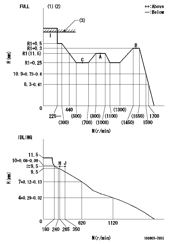
N:Pump speed
R:Rack position (mm)
(1)Torque cam stamping: T1
(2)Tolerance for racks not indicated: +-0.05mm.
(3)RACK LIMIT
----------
T1=H09
----------
----------
T1=H09
----------
Speed control lever angle
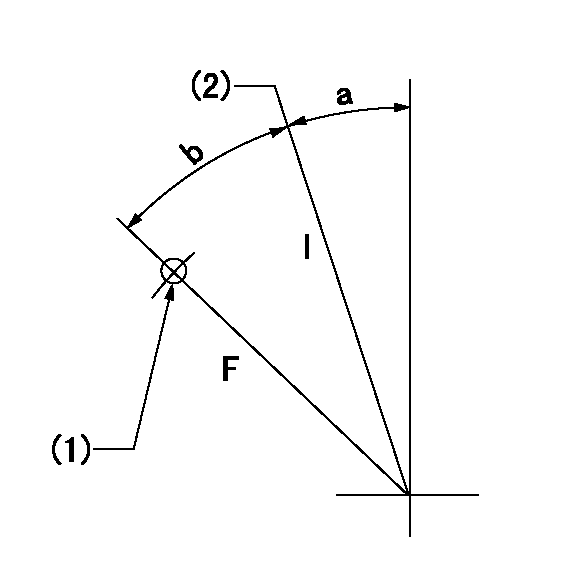
F:Full speed
I:Idle
(1)Use the pin at R = aa
(2)Stopper bolt set position 'H'
----------
aa=35mm
----------
a=11deg+-5deg b=36deg+-3deg
----------
aa=35mm
----------
a=11deg+-5deg b=36deg+-3deg
Stop lever angle
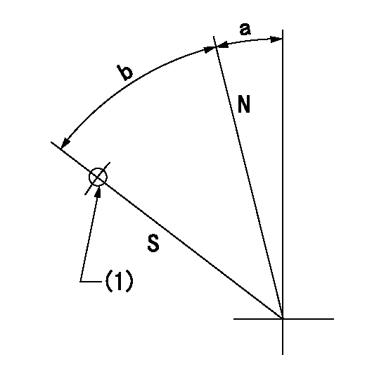
N:Pump normal
S:Stop the pump.
(1)Use the pin at R = aa
----------
aa=45mm
----------
a=12.5deg+-5deg b=40deg+-5deg
----------
aa=45mm
----------
a=12.5deg+-5deg b=40deg+-5deg
0000001501 TAMPER PROOF
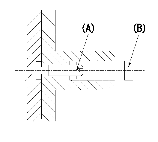
1. Set the full load.
(1)After governor adjustment (torque cam phase adjustment), move the load lever to increase the full rack position to R1.
(2)Set using the screw (A) so that the rack position is as shown above and tighten the locknut.
(3)Again set in the correct rack position using the load lever.
----------
R1=0.4mm
----------
----------
R1=0.4mm
----------
Timing setting
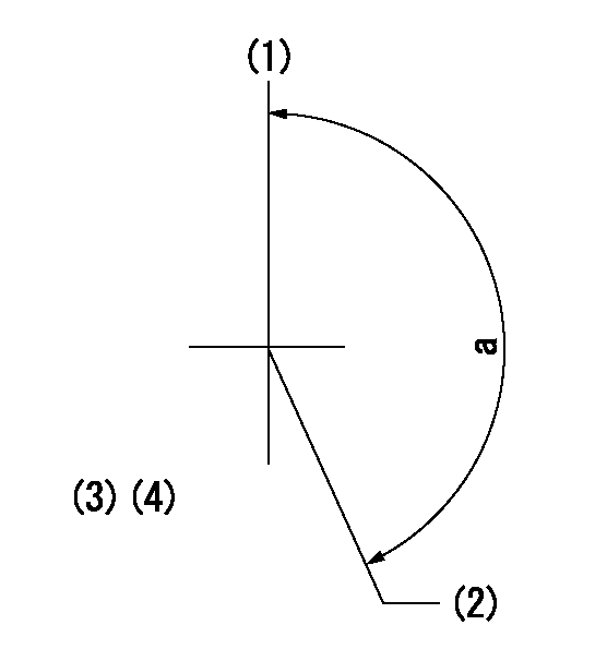
(1)Pump vertical direction
(2)Position of timer's threaded hole at No 1 cylinder's beginning of injection
(3)B.T.D.C.: aa
(4)-
----------
aa=14deg
----------
a=(150deg)
----------
aa=14deg
----------
a=(150deg)
Information:
This Program can only be administeredafter a failure occurs. The decision whether to apply the Program is madeby the dealer. When reporting the repair, use "PS50714" as the Part numberand "7755" as the Group Number. Use "96" as the Warranty Claim DescriptionCode and use "Z" as the SIMS Description Code. The information supplied in this serviceletter may not be valid after the termination date of this program. Donot perform the work outlined in this Service Letter after the terminationdate without first contacting your Caterpillar product analyst.TERMINATION DATE
November 30, 2005PROBLEM
The fuel injectors on certain 3126B HEUI TruckEngines need to be replaced. Some 3126B engines may have excessive oilconsumption as a result of oil leaking past an internal injector O-ring.AFFECTED PRODUCT
Model Identification Number
3126B 7AS1-75774PARTS NEEDED
Qty
Part Number Description
6 0R9348 INJECTOR GP
6 0R9349 INJECTOR GP
6 0R9350 INJECTOR GP
6 1093207 SEAL-O-RING
6 1333715 RING BACKUP
6 1482903 SEAL-O-RING
6 1495240 RING BACKUP
6 1504105 RING BACKUP
6 2373800 SEAL-O-RING If REMAN is not available the followingpart numbers can be used. A total of 6 injectors needed per engine repair.See SIS Web to determine the injector to be used.
Qty
Part Number Description
6 1881320 INJECTOR GP
6 1961401 INJECTOR GP
6 1964229 INJECTOR GP
6 2184109 INJECTOR GPACTION REQUIRED
If oil consumption suddenly increases and exceeds1/2 Gallon of oil per day and if the engine does not show traditional signsof oil consumption such as blowby or smoke, replace all 6 injectors. Refer to D&A RENR1369 for the injectoruninstall/install procedure.SERVICE CLAIM ALLOWANCES
Product smu Caterpillar Dealer Suggested Customer Suggested
Parts Labor Hrs Parts Labor Hrs Parts Labor Hrs
0-150,000 miles37-60 mos 70% 3.3 0 0 30% 1.3
150,001-200,000 miles37-60 mos 50% 2.3 0 0 50% 2.3
200,001-250,000 miles37-60 mos 25% 1.2 0 0 75% 3.4
This is a 4.6?hr job.PARTS DISPOSITION
Handle the parts in accordance with your WarrantyBulletin on warranty parts handling.