Information injection-pump assembly
BOSCH
9 400 615 216
9400615216
ZEXEL
101603-7811
1016037811
ISUZU
1156027861
1156027861

Rating:
Service parts 101603-7811 INJECTION-PUMP ASSEMBLY:
1.
_
7.
COUPLING PLATE
8.
_
9.
_
11.
Nozzle and Holder
1-15300-266-4
12.
Open Pre:MPa(Kqf/cm2)
18.1{185}
15.
NOZZLE SET
Include in #1:
101603-7811
as INJECTION-PUMP ASSEMBLY
Include in #2:
104741-5325
as _
Cross reference number
BOSCH
9 400 615 216
9400615216
ZEXEL
101603-7811
1016037811
ISUZU
1156027861
1156027861
Zexel num
Bosch num
Firm num
Name
101603-7811
9 400 615 216
1156027861 ISUZU
INJECTION-PUMP ASSEMBLY
6BG1-TC1 K
6BG1-TC1 K
Calibration Data:
Adjustment conditions
Test oil
1404 Test oil ISO4113 or {SAEJ967d}
1404 Test oil ISO4113 or {SAEJ967d}
Test oil temperature
degC
40
40
45
Nozzle and nozzle holder
105780-8140
Bosch type code
EF8511/9A
Nozzle
105780-0000
Bosch type code
DN12SD12T
Nozzle holder
105780-2080
Bosch type code
EF8511/9
Opening pressure
MPa
17.2
Opening pressure
kgf/cm2
175
Injection pipe
Outer diameter - inner diameter - length (mm) mm 6-2-600
Outer diameter - inner diameter - length (mm) mm 6-2-600
Overflow valve
131424-4920
Overflow valve opening pressure
kPa
127
107
147
Overflow valve opening pressure
kgf/cm2
1.3
1.1
1.5
Tester oil delivery pressure
kPa
157
157
157
Tester oil delivery pressure
kgf/cm2
1.6
1.6
1.6
Direction of rotation (viewed from drive side)
Right R
Right R
Injection timing adjustment
Direction of rotation (viewed from drive side)
Right R
Right R
Injection order
1-5-3-6-
2-4
Pre-stroke
mm
3.6
3.55
3.65
Rack position
After adjusting injection quantity. R=A
After adjusting injection quantity. R=A
Beginning of injection position
Drive side NO.1
Drive side NO.1
Difference between angles 1
Cal 1-5 deg. 60 59.5 60.5
Cal 1-5 deg. 60 59.5 60.5
Difference between angles 2
Cal 1-3 deg. 120 119.5 120.5
Cal 1-3 deg. 120 119.5 120.5
Difference between angles 3
Cal 1-6 deg. 180 179.5 180.5
Cal 1-6 deg. 180 179.5 180.5
Difference between angles 4
Cyl.1-2 deg. 240 239.5 240.5
Cyl.1-2 deg. 240 239.5 240.5
Difference between angles 5
Cal 1-4 deg. 300 299.5 300.5
Cal 1-4 deg. 300 299.5 300.5
Injection quantity adjustment
Adjusting point
-
Rack position
13.2
Pump speed
r/min
850
850
850
Average injection quantity
mm3/st.
95.7
94.1
97.3
Max. variation between cylinders
%
0
-2.5
2.5
Basic
*
Fixing the rack
*
Standard for adjustment of the maximum variation between cylinders
*
Injection quantity adjustment_02
Adjusting point
H
Rack position
9.5+-0.5
Pump speed
r/min
275
275
275
Average injection quantity
mm3/st.
8
6.7
9.3
Max. variation between cylinders
%
0
-14
14
Fixing the rack
*
Standard for adjustment of the maximum variation between cylinders
*
Injection quantity adjustment_03
Adjusting point
A
Rack position
R1(13.2)
Pump speed
r/min
850
850
850
Average injection quantity
mm3/st.
95.7
94.7
96.7
Basic
*
Fixing the lever
*
Boost pressure
kPa
34.7
34.7
Boost pressure
mmHg
260
260
Injection quantity adjustment_04
Adjusting point
B
Rack position
R1-0.15
Pump speed
r/min
1400
1400
1400
Average injection quantity
mm3/st.
96.7
93.5
99.9
Fixing the lever
*
Boost pressure
kPa
34.7
34.7
Boost pressure
mmHg
260
260
Injection quantity adjustment_05
Adjusting point
C
Rack position
R2(R1-0.
55)
Pump speed
r/min
550
550
550
Average injection quantity
mm3/st.
77
73.8
80.2
Fixing the lever
*
Boost pressure
kPa
34.7
34.7
Boost pressure
mmHg
260
260
Injection quantity adjustment_06
Adjusting point
D
Rack position
R2-1.5
Pump speed
r/min
550
550
550
Average injection quantity
mm3/st.
54
50.8
57.2
Fixing the lever
*
Boost pressure
kPa
0
0
0
Boost pressure
mmHg
0
0
0
Injection quantity adjustment_07
Adjusting point
I
Rack position
-
Pump speed
r/min
150
150
150
Average injection quantity
mm3/st.
93
93
125
Fixing the lever
*
Boost pressure
kPa
0
0
0
Boost pressure
mmHg
0
0
0
Boost compensator adjustment
Pump speed
r/min
550
550
550
Rack position
R2-1.5
Boost pressure
kPa
3.3
3.3
6
Boost pressure
mmHg
25
25
45
Boost compensator adjustment_02
Pump speed
r/min
550
550
550
Rack position
R2(R1-0.
55)
Boost pressure
kPa
21.3
21.3
21.3
Boost pressure
mmHg
160
160
160
Timer adjustment
Pump speed
r/min
(1170)
Advance angle
deg.
0
0
0
Remarks
Start
Start
Timer adjustment_02
Pump speed
r/min
1325
Advance angle
deg.
1.5
1
2
Timer adjustment_03
Pump speed
r/min
1400
Advance angle
deg.
2
1.5
2.5
Remarks
Finish
Finish
Test data Ex:
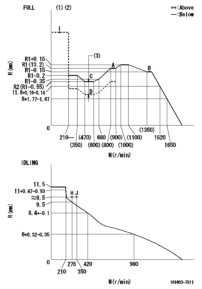
Governor adjustment

N:Pump speed
R:Rack position (mm)
(1)Torque cam stamping: T1
(2)Tolerance for racks not indicated: +-0.05mm.
(3)Boost compensator stroke: BCL
----------
T1=F36 BCL=1.5+-0.1mm
----------
----------
T1=F36 BCL=1.5+-0.1mm
----------
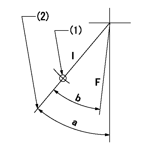
Speed control lever angle

F:Full speed
I:Idle
(1)Use the hole at R = aa
(2)Stopper bolt set position 'H'
----------
aa=35mm
----------
a=39.5deg+-5deg b=(37deg)+-3deg
----------
aa=35mm
----------
a=39.5deg+-5deg b=(37deg)+-3deg
Stop lever angle

N:Pump normal
S:Stop the pump.
----------
----------
a=25deg+-5deg b=40deg+-5deg
----------
----------
a=25deg+-5deg b=40deg+-5deg
0000001501 I/P WITH LOAD PLUNGER ADJ
Plunger assembly number: PL (stamping: ST)
1. Adjustment procedures
(1)Insert the pre-stroke adjusting shims L1 for each cylinder.
(2)Adjust injection quantity.(max. var. bet. cyl. idling a1, full a2)
(3)At basic point A, adjust so that the pre-stroke is L2.
(4)Reconfirm the injection quantity.
----------
PL=131153-3720 ST=A716 L1=1mm L2=3.6+-0.05mm a1=+-14% a2=+-2.5%
----------
----------
PL=131153-3720 ST=A716 L1=1mm L2=3.6+-0.05mm a1=+-14% a2=+-2.5%
----------
Timing setting

(1)Pump vertical direction
(2)Position of timer's threaded hole at No 1 cylinder's beginning of injection
(3)B.T.D.C.: aa
(4)-
----------
aa=10deg
----------
a=(60deg)
----------
aa=10deg
----------
a=(60deg)
Information:
This Program must be administered as soon as possible. When reporting the repair, use "PI3325" as the Part Number, "7751" as the Group Number, "56" as the Warranty Claim Description Code and "T" as the SIMS Description Code. Exception: If the repair is done after failure, use "PI3325" as the Part Number, "7751" as the Group Number, "96" as the Warranty Claim Description Code, and "Z" as the SIMS Description Code.
Completion Date
February 29, 2000Termination Date
February 29, 2000Problem
Upgrade software needs to be installed on certain 3606, 3608, 3612, and 3616 diesel engines with the Marine Monitoring System (MMS) to become Y2K compatible.
Affected Product
Model & Identification Number
3606 (8RB29, 8RB656-661, 8RB669, 8RB672-673, 8RB680-688, 8RB691-00692, 8RB695-702, 8RB711-00713, 8RB715, 8RB717-718, 8RB721-723)
3608 (6MC535-536, 6MC550, 6MC561-562, 6MC582-586)
3612 (9RC230, 9RC242, 9RC247-253, 9RC256-257, 9RC259-260)
3616 (1PD289-293, 1PD295, 1PD306, 1PD308, 1PD313-336)
Parts Needed
- Dealers will need to obtain the Upgrade Files for this program.- 1 Blank formatted 1.44 MB floppy disk for Winfile Upgrade- 6 Blank formatted 1.44 MB floppy disks for InTouch 5.6B UpgradeAction Required
See the attached procedure.
Owner Notification
U.S. and Canadian owners will receive the attached Owner Notification.
Service Claim Allowances
This is a 1-hour job.
U.S. and Canadian Dealers Only - Eligible dealers may enter a Type 2 SIMS Report.
Parts Disposition
Handle the parts in accordance with your Warranty Bulletin on warranty parts handling.
MAKE EVERY EFFORT TO COMPLETE THIS PROGRAM AS SOON AS POSSIBLE.
Attach.(1-Owner Notification)(1-Rework Procedure)Copy Of Owner Notification For U.S. And Canadian Owners
Rework Procedure
Windows 3.11 Winfile Upgrade
This upgrade is necessary for Windows 3.11 to correctly date stamp files after the year 2000, The first three steps in the following procedure will be done in the office or shop.
1. Obtain the file. The file can be obtained from the Caterpillar Mailbox, SISWEB, or from the SIS disks that are released monthly. The file part number is 174-8693.2. Unzip the file. The 174-8693.exe file is a self-executing zip file. To Unzip, place the file in a known location on the hard drive. Run the file. At the dialog box type in 'A:\' where it asks for the folder to place unzipped files. Install a blank formatted disk into the A: drive. Select UNZIP or press "ENTER". This will unzip the files to the floppy drive. If your floppy drive is not 'A:' substitute your floppy drive letter for A in the above instuctions.)
3. Label the disk. This disk should be labeled "Winfile.exe Y2K Upgrade". This disk or a copy of this disk can be used to do multiple upgrades. It is not necessary to repeat steps 1-3 for each upgrade.4. Perform the upgrade. The upgrade should be done from the DOS prompt. Attach a keyboard to the MMS computer. With the MMS program running press "ALT"and "F4" at the same time. This will exit the MMS program. Press "ALT"and "F4" at the same time again and you will get a dialog box that asks you to confirm you want to end your Windows session. Press "ENTER" to confirm. Install the floppy labeled "Winfile.exe Y2K Upgrade" into the floppy drive on the MMS
Have questions with 101603-7811?
Group cross 101603-7811 ZEXEL
Isuzu
101603-7811
9 400 615 216
1156027861
INJECTION-PUMP ASSEMBLY
6BG1-TC1
6BG1-TC1
