Information injection-pump assembly
ZEXEL
101603-7770
1016037770
ISUZU
1156027790
1156027790

Rating:
Cross reference number
ZEXEL
101603-7770
1016037770
ISUZU
1156027790
1156027790
Zexel num
Bosch num
Firm num
Name
101603-7770
1156027790 ISUZU
INJECTION-PUMP ASSEMBLY
6SA1 * K
6SA1 * K
Calibration Data:
Adjustment conditions
Test oil
1404 Test oil ISO4113 or {SAEJ967d}
1404 Test oil ISO4113 or {SAEJ967d}
Test oil temperature
degC
40
40
45
Nozzle and nozzle holder
105780-8140
Bosch type code
EF8511/9A
Nozzle
105780-0000
Bosch type code
DN12SD12T
Nozzle holder
105780-2080
Bosch type code
EF8511/9
Opening pressure
MPa
17.2
Opening pressure
kgf/cm2
175
Injection pipe
Outer diameter - inner diameter - length (mm) mm 6-2-600
Outer diameter - inner diameter - length (mm) mm 6-2-600
Overflow valve
132424-0620
Overflow valve opening pressure
kPa
157
123
191
Overflow valve opening pressure
kgf/cm2
1.6
1.25
1.95
Tester oil delivery pressure
kPa
157
157
157
Tester oil delivery pressure
kgf/cm2
1.6
1.6
1.6
Direction of rotation (viewed from drive side)
Left L
Left L
Injection timing adjustment
Direction of rotation (viewed from drive side)
Left L
Left L
Injection order
1-5-3-6-
2-4
Pre-stroke
mm
3.2
3.15
3.25
Beginning of injection position
Governor side NO.1
Governor side NO.1
Difference between angles 1
Cal 1-5 deg. 60 59.5 60.5
Cal 1-5 deg. 60 59.5 60.5
Difference between angles 2
Cal 1-3 deg. 120 119.5 120.5
Cal 1-3 deg. 120 119.5 120.5
Difference between angles 3
Cal 1-6 deg. 180 179.5 180.5
Cal 1-6 deg. 180 179.5 180.5
Difference between angles 4
Cyl.1-2 deg. 240 239.5 240.5
Cyl.1-2 deg. 240 239.5 240.5
Difference between angles 5
Cal 1-4 deg. 300 299.5 300.5
Cal 1-4 deg. 300 299.5 300.5
Injection quantity adjustment
Adjusting point
-
Rack position
12
Pump speed
r/min
700
700
700
Average injection quantity
mm3/st.
88.1
86.5
89.7
Max. variation between cylinders
%
0
-2.5
2.5
Basic
*
Fixing the rack
*
Standard for adjustment of the maximum variation between cylinders
*
Injection quantity adjustment_02
Adjusting point
H
Rack position
9.5+-0.5
Pump speed
r/min
260
260
260
Average injection quantity
mm3/st.
9
7
11
Max. variation between cylinders
%
0
-14
14
Fixing the rack
*
Standard for adjustment of the maximum variation between cylinders
*
Injection quantity adjustment_03
Adjusting point
A
Rack position
R1(12)
Pump speed
r/min
700
700
700
Average injection quantity
mm3/st.
88.1
87.1
89.1
Basic
*
Fixing the lever
*
Injection quantity adjustment_04
Adjusting point
B
Rack position
R1+0.2
Pump speed
r/min
1350
1350
1350
Average injection quantity
mm3/st.
101.5
98.3
104.7
Fixing the lever
*
Injection quantity adjustment_05
Adjusting point
C
Rack position
(R1-0.15
)
Pump speed
r/min
550
550
550
Average injection quantity
mm3/st.
80.4
77.2
83.6
Fixing the lever
*
Injection quantity adjustment_06
Adjusting point
I
Rack position
-
Pump speed
r/min
100
100
100
Each cylinder's injection qty
mm3/st.
107
107
117
Fixing the lever
*
Rack limit
*
Timer adjustment
Pump speed
r/min
850--
Advance angle
deg.
0
0
0
Remarks
Start
Start
Timer adjustment_02
Pump speed
r/min
800
Advance angle
deg.
0.5
Timer adjustment_03
Pump speed
r/min
1000
Advance angle
deg.
1
0.5
1.5
Timer adjustment_04
Pump speed
r/min
1200
Advance angle
deg.
2.3
1.8
2.8
Timer adjustment_05
Pump speed
r/min
1350
Advance angle
deg.
3.5
3
4
Remarks
Finish
Finish
Test data Ex:
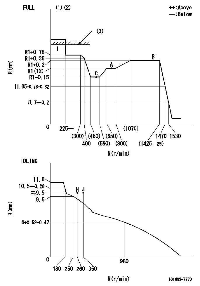
Governor adjustment

N:Pump speed
R:Rack position (mm)
(1)Torque cam stamping: T1
(2)Tolerance for racks not indicated: +-0.05mm.
(3)RACK LIMIT
----------
T1=D63
----------
----------
T1=D63
----------
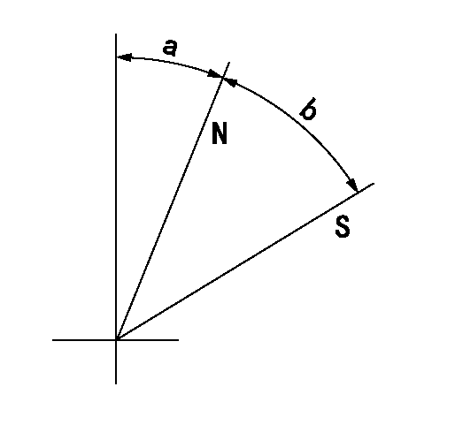
Speed control lever angle

F:Full speed
I:Idle
(1)Stopper bolt set position 'H'
----------
----------
a=18deg+-5deg b=40deg+-3deg
----------
----------
a=18deg+-5deg b=40deg+-3deg
Stop lever angle

N:Pump normal
S:Stop the pump.
----------
----------
a=25deg+-5deg b=40deg+-5deg
----------
----------
a=25deg+-5deg b=40deg+-5deg
0000001501 TAMPER PROOF

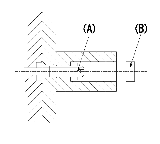
1. Set the full load.
(1)After governor adjustment (torque cam phase adjustment), move the load lever to increase the full rack position to R1.
(2)Set using the screw (A) so that the rack position is as shown above and tighten the locknut.
(3)Again set in the correct rack position using the load lever.
----------
R1=0.4mm
----------
----------
R1=0.4mm
----------
Timing setting

(1)Pump vertical direction
(2)Position of timer's threaded hole at No 1 cylinder's beginning of injection
(3)B.T.D.C.: aa
(4)-
----------
aa=20deg
----------
a=(40deg)
----------
aa=20deg
----------
a=(40deg)
Information:
This Program must be administered as soon as possible. When reporting the repair, use "PI1324" as the Part Number, "7751" as the Group Number, "56" as the Warranty Claim Description Code and "T" as the SIMS Description Code. Exception: If the repair is done after failure, use "PI1324" as the Part Number, "7751" as the Group Number, "96" as the Warranty Claim Description Code, and "Z" as the SIMS Description Code.
Problem
The 1206437 and 1206438 Couplings used in the 1218021, 1218022, 1218023, and 1218024 Lines Group may slip off of the water piping during operation causing hot engine jacket water to escape from the jacket water circuit.Affected Product
Model & Identification Number
3606 (8RB571, 8RB588, 8RB589, 8RB599, 8RB600, 8RB610, 8RB614-617, 8RB631, 8RB632, 8RB634 , 8RB635)
3608 (6MC489-499, 6MC511, 6MC517, 6MC519, 6MC529)
3612 (9RC167, 9RC168, 9RC185, 9RC187, 9RC190, 9RC192, 9RC199, 9RC201-203, 9RC205, 9RC209-211 , 9RC213, 9RC217, 9RC223)
3616 (1PD184, 1PD198-205, 1PD207-211, 1PD223, 1PD224, 1PD226-231, 1PD237, 1PD238, 1PD245-248 , 1PD250, 1PD254-259, 1PD267, 1PD268)
Parts Needed
4 - 3E7424 Clamp4 - 1242732 Clamp1 - 1378788 Connector1 - 1378789 Connector1 - 1389817 Tube1 - 1389818 TubeAction Required
See attached rework procedure.
Owner Notification
U.S. and Canadian owners will receive the attached Owner Notification.
Service Claim Allowances
Parts Disposition
Handle the parts in accordance with your Warranty Bulletin on warranty parts handling.
MAKE EVERY EFFORT TO COMPLETE THIS PROGRAM AS SOON AS POSSIBLE.
Attach.(1-Owner Notification)(2-Rework Procedure)Copy Of Owner Notification For U.S. And Canadian Owners
Rework Procedure
Procedure: Jacket Water Pump Inlet Connector - Illustration 1
1. Remove the old 1206437 Coupling.2. Measure the gap between the tube ends.If the dimension is within tolerance (104 10 mm) then skip to Step 4. If the tube is not within tolerance, it will need to be removed and either lengthened, or shortened, using the tube provided.3. If lengthening the tube, cut the tube far enough away from the expanded end that the 1389817 Extension will not extend past the taper inside the tube. If shortening the tube, cut and remove a section from the tube of appropriate length, and rejoin the tube by welding the 1389817 Extension between the two halves.4. Install the new 1378788 Coupling. Note that the short end of the coupling goes on the pump side. Tighten the 1242732 Hose Clamps to
Have questions with 101603-7770?
Group cross 101603-7770 ZEXEL
Isuzu
Isuzu
101603-7770
1156027790
INJECTION-PUMP ASSEMBLY
6SA1
6SA1