Information injection-pump assembly
BOSCH
9 400 615 208
9400615208
ZEXEL
101603-7721
1016037721
ISUZU
8943933422
8943933422
Rating:
Service parts 101603-7721 INJECTION-PUMP ASSEMBLY:
1.
_
7.
COUPLING PLATE
8.
_
9.
_
11.
Nozzle and Holder
8-94397-483-2
12.
Open Pre:MPa(Kqf/cm2)
18.1{185}

15.
NOZZLE SET
Include in #1:
101603-7721
as INJECTION-PUMP ASSEMBLY
Include in #2:
104741-6890
as _
Cross reference number
BOSCH
9 400 615 208
9400615208
ZEXEL
101603-7721
1016037721
ISUZU
8943933422
8943933422
Zexel num
Bosch num
Firm num
Name
101603-7721
9 400 615 208
8943933422 ISUZU
INJECTION-PUMP ASSEMBLY
6HE1-S * K
6HE1-S * K
Calibration Data:
Adjustment conditions
Test oil
1404 Test oil ISO4113 or {SAEJ967d}
1404 Test oil ISO4113 or {SAEJ967d}
Test oil temperature
degC
40
40
45
Nozzle and nozzle holder
105780-8140
Bosch type code
EF8511/9A
Nozzle
105780-0000
Bosch type code
DN12SD12T
Nozzle holder
105780-2080
Bosch type code
EF8511/9
Opening pressure
MPa
17.2
Opening pressure
kgf/cm2
175
Injection pipe
Outer diameter - inner diameter - length (mm) mm 6-2-600
Outer diameter - inner diameter - length (mm) mm 6-2-600
Overflow valve
131424-4920
Overflow valve opening pressure
kPa
127
107
147
Overflow valve opening pressure
kgf/cm2
1.3
1.1
1.5
Tester oil delivery pressure
kPa
157
157
157
Tester oil delivery pressure
kgf/cm2
1.6
1.6
1.6
Direction of rotation (viewed from drive side)
Left L
Left L
Injection timing adjustment
Direction of rotation (viewed from drive side)
Left L
Left L
Injection order
1-5-3-6-
2-4
Pre-stroke
mm
4.2
4.15
4.25
Rack position
After adjusting injection quantity. R=A
After adjusting injection quantity. R=A
Beginning of injection position
Governor side NO.1
Governor side NO.1
Difference between angles 1
Cal 1-5 deg. 60 59.5 60.5
Cal 1-5 deg. 60 59.5 60.5
Difference between angles 2
Cal 1-3 deg. 120 119.5 120.5
Cal 1-3 deg. 120 119.5 120.5
Difference between angles 3
Cal 1-6 deg. 180 179.5 180.5
Cal 1-6 deg. 180 179.5 180.5
Difference between angles 4
Cyl.1-2 deg. 240 239.5 240.5
Cyl.1-2 deg. 240 239.5 240.5
Difference between angles 5
Cal 1-4 deg. 300 299.5 300.5
Cal 1-4 deg. 300 299.5 300.5
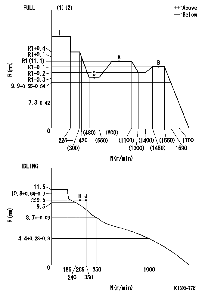
Injection quantity adjustment
Adjusting point
-
Rack position
11.1
Pump speed
r/min
900
900
900
Average injection quantity
mm3/st.
66.9
65.3
68.5
Max. variation between cylinders
%
0
-2.5
2.5
Basic
*
Fixing the rack
*
Standard for adjustment of the maximum variation between cylinders
*
Injection quantity adjustment_02
Adjusting point
H
Rack position
9.5+-0.5
Pump speed
r/min
265
265
265
Average injection quantity
mm3/st.
9
7.7
10.3
Max. variation between cylinders
%
0
-14
14
Fixing the rack
*
Standard for adjustment of the maximum variation between cylinders
*
Injection quantity adjustment_03
Adjusting point
A
Rack position
R1(11.1)
Pump speed
r/min
900
900
900
Average injection quantity
mm3/st.
66.9
65.9
67.9
Basic
*
Fixing the lever
*
Injection quantity adjustment_04
Adjusting point
B
Rack position
R1-0.1
Pump speed
r/min
1500
1500
1500
Average injection quantity
mm3/st.
78.5
74.5
82.5
Fixing the lever
*
Injection quantity adjustment_05
Adjusting point
C
Rack position
R1-0.3
Pump speed
r/min
600
600
600
Average injection quantity
mm3/st.
49.7
46.5
52.9
Fixing the lever
*
Injection quantity adjustment_06
Adjusting point
I
Rack position
-
Pump speed
r/min
150
150
150
Average injection quantity
mm3/st.
99
99
131
Fixing the lever
*
Timer adjustment
Pump speed
r/min
1210--
Advance angle
deg.
0
0
0
Load
3/4
Remarks
Start
Start
Timer adjustment_02
Pump speed
r/min
1160
Advance angle
deg.
0.3
Load
3/4
Timer adjustment_03
Pump speed
r/min
1500
Advance angle
deg.
5.5
5
6
Load
4/4
Remarks
Finish
Finish
Test data Ex:
Governor adjustment
N:Pump speed
R:Rack position (mm)
(1)Torque cam stamping: T1
(2)Tolerance for racks not indicated: +-0.05mm.
----------
T1=G22
----------
----------
T1=G22
----------
Speed control lever angle

F:Full speed
I:Idle
(1)Use the pin at R = aa
(2)Stopper bolt set position 'H'
----------
aa=35mm
----------
a=11deg+-5deg b=38deg+-3deg
----------
aa=35mm
----------
a=11deg+-5deg b=38deg+-3deg
Stop lever angle

N:Pump normal
S:Stop the pump.
(1)Use the pin at R = aa
----------
aa=62.5mm
----------
a=12.5deg+-5deg b=29deg+-5deg
----------
aa=62.5mm
----------
a=12.5deg+-5deg b=29deg+-5deg
0000001501 I/P WITH LOAD PLUNGER ADJ
Plunger assembly number: PL (stamping: ST)
1. Adjustment procedures
(1)Insert the pre-stroke adjusting shims L1 for each cylinder.
(2)Adjust injection quantity.(max. var. bet. cyl. idling a1, full a2)
(3)At basic point A, adjust so that the pre-stroke is L2.
(4)Reconfirm the injection quantity.
----------
PL=131153-4520 ST=A724 L1=1mm L2=4.2+-0.05mm a1=+-14% a2=+-2.5%
----------
----------
PL=131153-4520 ST=A724 L1=1mm L2=4.2+-0.05mm a1=+-14% a2=+-2.5%
----------
Timing setting
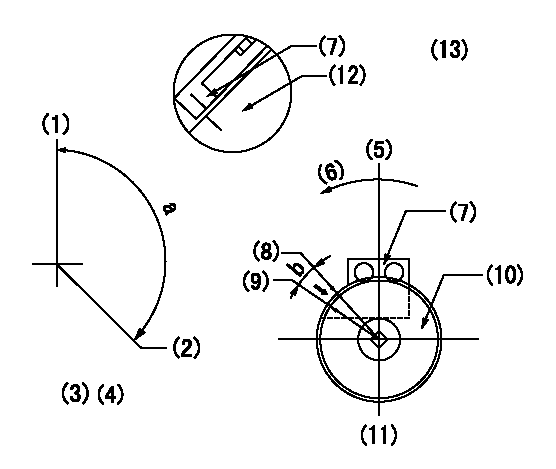
(1)Pump vertical direction
(2)Position of timer's threaded hole at No 1 cylinder's beginning of injection
(3)B.T.D.C.: aa
(4)-
(5)Pump vertical direction
(6)Direction of rotation
(7)Pointer
(8)Pointer stamping
(9)Timing device stamping
(10)Timing device
(11)Stamp both at the same time as shown above.
(12)Outside circumference of timing device
(13)Secondary timing stamping position for the No. 1 cylinder's beginning of injection
----------
aa=11deg bb=1deg
----------
a=(150deg)
----------
aa=11deg bb=1deg
----------
a=(150deg)
Information:
Parts Needed
Group 1
6 - 1136145 Seat6 - 1136303 Seal-O-Ring1 - 1192940 Gasket6 - 1249714 Tube Assembly6 - 1265424 Clamp-InjectorGroup 2
6 - 0R4970 Injector (for 230 HP and Above)6 - 0R4972 Injector (for 210 HP and Below)6 - 1136303 Seal O-Ring (if not included in group 1)6 - 1148718 Seal O-Ring1 - 1192940 Gasket (if not included in group 1)6 - 1231199 Seal6 - 1258274 Seal O-RingAction Required
See attached rework procedure.
Service Claim Allowances
Group 1
Affected Product
* After failure repairs made prior to January 1, 1996 should claim actual reasonable time. * After failure repairs made January 1, 1996 or later should use the 3126 Time Requirement Guide to determine additional labor hours.
* Before failure repair should claim the labor hours listed below:
If Group 1 and Group 2 repairs are performed, claim Group 2 SMCS Codes ONLY.
Add an additional 1.6 Hours to both groups 1 and 2 if the procedure is done in a motor home.
Parts Stock
Submit one claim for all 1249714 Tube Assemblies removed from Parts Stock.
US and Canadian Dealers Only - When submitting a Parts Stock claim use 99Z00007 in the Product Identification Number Field.
TEPS/MEPS dealers must return the affected Parts Stock to their Caterpillar dealer for replacement.
Group 2
Add an additional 1.6 Hours to both groups 1 and 2 if the procedure is done in a motor home.
Parts Disposition
Handle the parts in accordance with your Warranty Bulletin on warranty parts handling.
Attach.(1-Rework Procedure)Rework Procedure
Group 1
Affected Product
Jumper Tube Removal
1. Loosen, but do not back off the jumper tube flare nut at the end nearest the high pressure oil manifold, using the 5P0144 Crow's Foot Socket.2. Remove the 8T0292 Bolt and the fuel injector hold-down clamp.3. Loosen and back out the #10 Allen head bolts at the fuel injector using the 1252584 Ball Head Hex Drive Bit (4mm). Leave the bolts in the jumper tube flange while removing the jumper tube. Retain the bolts for reassembly.4. Stabilize the top of the tube with one finger and back out the nut at the mainfold end of the tube.5. Carefully remove the jumper tube from the fuel injector and oil manifold.6. Remove the jumper tube seat and O-ring from the top of the fuel injector. A magnet is recommended for picking up the seat.
7. Retain the removed jumper tube, seat, and O-ring until the warranty claim is processed.Jumper Tube Installation
1. Place a new 1136303 O-Ring into the channel on top of the fuel injector. Do not use STP to lube O-rings. STP traps moisture and will cause rust buildup in the O-ring groove.
2. Place a new 1136145 Jumper Tube Seat over the O-ring on top of the injector. The earlier tubes have a shiny appearance on the two bolt flange. The new tubes have a phosphate and oil coating, which is black, similar in color to an internal engine bolt.
The following guidelines should be used to identify parts in the system. The date code on the 1249714 Tube plastic wrapper is in the form 01996476. The first four numbers represent the month and year,
Group 1
6 - 1136145 Seat6 - 1136303 Seal-O-Ring1 - 1192940 Gasket6 - 1249714 Tube Assembly6 - 1265424 Clamp-InjectorGroup 2
6 - 0R4970 Injector (for 230 HP and Above)6 - 0R4972 Injector (for 210 HP and Below)6 - 1136303 Seal O-Ring (if not included in group 1)6 - 1148718 Seal O-Ring1 - 1192940 Gasket (if not included in group 1)6 - 1231199 Seal6 - 1258274 Seal O-RingAction Required
See attached rework procedure.
Service Claim Allowances
Group 1
Affected Product
* After failure repairs made prior to January 1, 1996 should claim actual reasonable time. * After failure repairs made January 1, 1996 or later should use the 3126 Time Requirement Guide to determine additional labor hours.
* Before failure repair should claim the labor hours listed below:
If Group 1 and Group 2 repairs are performed, claim Group 2 SMCS Codes ONLY.
Add an additional 1.6 Hours to both groups 1 and 2 if the procedure is done in a motor home.
Parts Stock
Submit one claim for all 1249714 Tube Assemblies removed from Parts Stock.
US and Canadian Dealers Only - When submitting a Parts Stock claim use 99Z00007 in the Product Identification Number Field.
TEPS/MEPS dealers must return the affected Parts Stock to their Caterpillar dealer for replacement.
Group 2
Add an additional 1.6 Hours to both groups 1 and 2 if the procedure is done in a motor home.
Parts Disposition
Handle the parts in accordance with your Warranty Bulletin on warranty parts handling.
Attach.(1-Rework Procedure)Rework Procedure
Group 1
Affected Product
Jumper Tube Removal
1. Loosen, but do not back off the jumper tube flare nut at the end nearest the high pressure oil manifold, using the 5P0144 Crow's Foot Socket.2. Remove the 8T0292 Bolt and the fuel injector hold-down clamp.3. Loosen and back out the #10 Allen head bolts at the fuel injector using the 1252584 Ball Head Hex Drive Bit (4mm). Leave the bolts in the jumper tube flange while removing the jumper tube. Retain the bolts for reassembly.4. Stabilize the top of the tube with one finger and back out the nut at the mainfold end of the tube.5. Carefully remove the jumper tube from the fuel injector and oil manifold.6. Remove the jumper tube seat and O-ring from the top of the fuel injector. A magnet is recommended for picking up the seat.
7. Retain the removed jumper tube, seat, and O-ring until the warranty claim is processed.Jumper Tube Installation
1. Place a new 1136303 O-Ring into the channel on top of the fuel injector. Do not use STP to lube O-rings. STP traps moisture and will cause rust buildup in the O-ring groove.
2. Place a new 1136145 Jumper Tube Seat over the O-ring on top of the injector. The earlier tubes have a shiny appearance on the two bolt flange. The new tubes have a phosphate and oil coating, which is black, similar in color to an internal engine bolt.
The following guidelines should be used to identify parts in the system. The date code on the 1249714 Tube plastic wrapper is in the form 01996476. The first four numbers represent the month and year,
Have questions with 101603-7721?
Group cross 101603-7721 ZEXEL
Isuzu
101603-7721
9 400 615 208
8943933422
INJECTION-PUMP ASSEMBLY
6HE1-S
6HE1-S