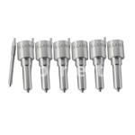
Information injection-pump assembly
ZEXEL
101603-7702
1016037702
ISUZU
8943931743
8943931743
Rating:
Service parts 101603-7702 INJECTION-PUMP ASSEMBLY:
1.
_
7.
COUPLING PLATE
8.
_
9.
_
11.
Nozzle and Holder
8-94397-483-2
12.
Open Pre:MPa(Kqf/cm2)
18.1{185}
15.
NOZZLE SET
Include in #1:
101603-7702
as INJECTION-PUMP ASSEMBLY
Include in #2:
104740-1911
as _
Cross reference number
ZEXEL
101603-7702
1016037702
ISUZU
8943931743
8943931743
Zexel num
Bosch num
Firm num
Name
Calibration Data:
Adjustment conditions
Test oil
1404 Test oil ISO4113 or {SAEJ967d}
1404 Test oil ISO4113 or {SAEJ967d}
Test oil temperature
degC
40
40
45
Nozzle and nozzle holder
105780-8140
Bosch type code
EF8511/9A
Nozzle
105780-0000
Bosch type code
DN12SD12T
Nozzle holder
105780-2080
Bosch type code
EF8511/9
Opening pressure
MPa
17.2
Opening pressure
kgf/cm2
175
Injection pipe
Outer diameter - inner diameter - length (mm) mm 6-2-600
Outer diameter - inner diameter - length (mm) mm 6-2-600
Overflow valve
131424-4920
Overflow valve opening pressure
kPa
127
107
147
Overflow valve opening pressure
kgf/cm2
1.3
1.1
1.5
Tester oil delivery pressure
kPa
157
157
157
Tester oil delivery pressure
kgf/cm2
1.6
1.6
1.6
Direction of rotation (viewed from drive side)
Left L
Left L
Injection timing adjustment
Direction of rotation (viewed from drive side)
Left L
Left L
Injection order
1-5-3-6-
2-4
Pre-stroke
mm
4.2
4.15
4.25
Rack position
After adjusting injection quantity. R=A
After adjusting injection quantity. R=A
Beginning of injection position
Governor side NO.1
Governor side NO.1
Difference between angles 1
Cal 1-5 deg. 60 59.5 60.5
Cal 1-5 deg. 60 59.5 60.5
Difference between angles 2
Cal 1-3 deg. 120 119.5 120.5
Cal 1-3 deg. 120 119.5 120.5
Difference between angles 3
Cal 1-6 deg. 180 179.5 180.5
Cal 1-6 deg. 180 179.5 180.5
Difference between angles 4
Cyl.1-2 deg. 240 239.5 240.5
Cyl.1-2 deg. 240 239.5 240.5
Difference between angles 5
Cal 1-4 deg. 300 299.5 300.5
Cal 1-4 deg. 300 299.5 300.5
Injection quantity adjustment
Adjusting point
-
Rack position
11.1
Pump speed
r/min
900
900
900
Average injection quantity
mm3/st.
66.9
65.3
68.5
Max. variation between cylinders
%
0
-2.5
2.5
Basic
*
Fixing the rack
*
Standard for adjustment of the maximum variation between cylinders
*
Injection quantity adjustment_02
Adjusting point
H
Rack position
9.5+-0.5
Pump speed
r/min
265
265
265
Average injection quantity
mm3/st.
9
7.7
10.3
Max. variation between cylinders
%
0
-14
14
Fixing the rack
*
Standard for adjustment of the maximum variation between cylinders
*
Injection quantity adjustment_03
Adjusting point
A
Rack position
R1(11.1)
Pump speed
r/min
900
900
900
Average injection quantity
mm3/st.
66.9
65.9
67.9
Basic
*
Fixing the lever
*
Injection quantity adjustment_04
Adjusting point
B
Rack position
R1-0.1
Pump speed
r/min
1500
1500
1500
Average injection quantity
mm3/st.
78.5
74.5
82.5
Fixing the lever
*
Injection quantity adjustment_05
Adjusting point
C
Rack position
R1-0.3
Pump speed
r/min
600
600
600
Average injection quantity
mm3/st.
49.7
46.5
52.9
Fixing the lever
*
Injection quantity adjustment_06
Adjusting point
I
Rack position
-
Pump speed
r/min
150
150
150
Average injection quantity
mm3/st.
99
99
131
Fixing the lever
*
Timer adjustment
Pump speed
r/min
1210--
Advance angle
deg.
0
0
0
Load
3/4
Remarks
Start
Start
Timer adjustment_02
Pump speed
r/min
1160
Advance angle
deg.
0.3
Load
3/4
Timer adjustment_03
Pump speed
r/min
1500
Advance angle
deg.
5.5
5
6
Load
4/4
Remarks
Finish
Finish
Test data Ex:
Governor adjustment
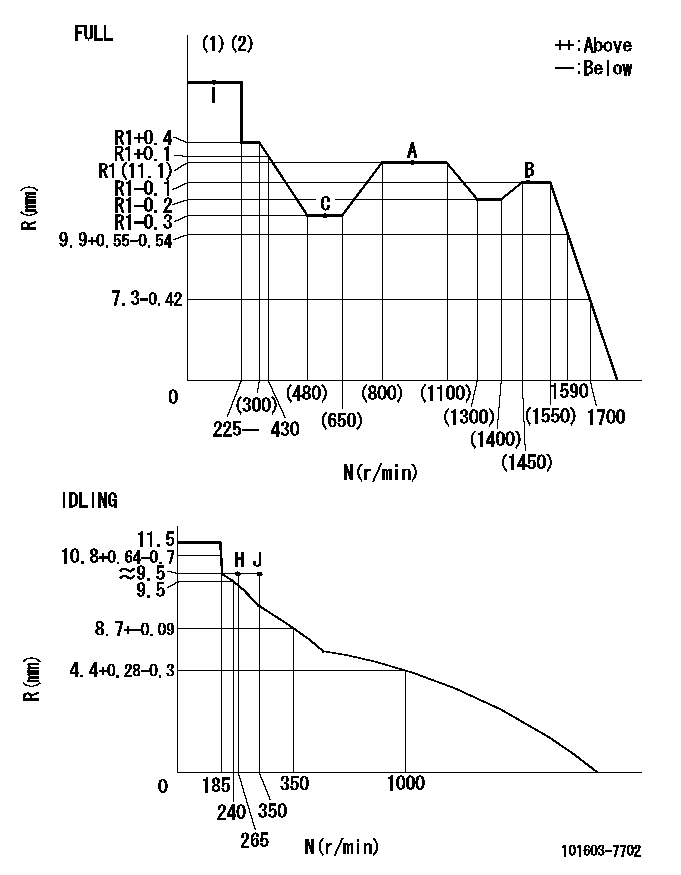
N:Pump speed
R:Rack position (mm)
(1)Torque cam stamping: T1
(2)Tolerance for racks not indicated: +-0.05mm.
----------
T1=G22
----------
----------
T1=G22
----------
Speed control lever angle
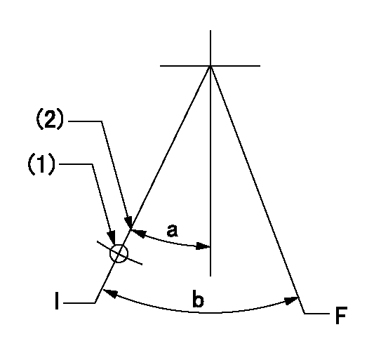
F:Full speed
I:Idle
(1)Use the hole at R = aa
(2)Stopper bolt set position 'H'
----------
aa=60mm
----------
a=28.5deg+-5deg b=38deg+-3deg
----------
aa=60mm
----------
a=28.5deg+-5deg b=38deg+-3deg
Stop lever angle
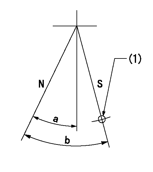
N:Pump normal
S:Stop the pump.
(1)Use the hole at R = aa
----------
aa=62.5mm
----------
a=25deg+-5deg b=29deg+-5deg
----------
aa=62.5mm
----------
a=25deg+-5deg b=29deg+-5deg
0000001501 I/P WITH LOAD PLUNGER ADJ
Plunger assembly number: PL (stamping: ST)
1. Adjustment procedures
(1)Insert the pre-stroke adjusting shims L1 for each cylinder.
(2)Adjust injection quantity.(max. var. bet. cyl. idling a1, full a2)
(3)At basic point A, adjust so that the pre-stroke is L2.
(4)Reconfirm the injection quantity.
----------
PL=131153-4520 ST=A724 L1=1mm L2=4.2+-0.05mm a1=+-14% a2=+-2.5%
----------
----------
PL=131153-4520 ST=A724 L1=1mm L2=4.2+-0.05mm a1=+-14% a2=+-2.5%
----------
Timing setting
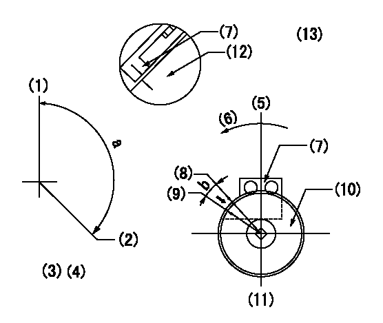
(1)Pump vertical direction
(2)Position of timer's threaded hole at No 1 cylinder's beginning of injection
(3)B.T.D.C.: aa
(4)-
(5)Pump vertical direction
(6)Direction of rotation
(7)Pointer
(8)Pointer stamping
(9)Timing device stamping
(10)Timing device
(11)Move b deg and stamp both at the same time as shown above.
(12)Outside circumference of timing device
(13)Secondary timing stamping position for the No. 1 cylinder's beginning of injection
----------
aa=11deg
----------
a=(150deg) b=1deg
----------
aa=11deg
----------
a=(150deg) b=1deg
Information:
The information supplied in this service letter may not be valid after the termination date of this program. Do not perform the work outlined in this Service Letter after the termination date without first contacting your Caterpillar product analyst.
This Program can only be administered after a failure occurs. The decision whether to apply the Program is made by the dealer. When reporting the repair, use "PS0843" as the Part Number and "7755" as the Group Number. Use "96" as the Warranty Claim Description Code and use "Z" as the SIMS Description Code.
This revised service letter replaces the April 25, 1995 (Revised April 1997) Service Letter. Changes have been made to the Termination Date.
Termination Date
December 31, 1998Problem
Low power complaints may be the result of a reduced fuel rate in the Electronic Unit Injectors of certain 3406E Truck Engines.
Affected Product
Model & Identification Number
3406E (5EK1-58999)
Parts Needed
Not applicable.
Action Required
When the customer's complaint is, "The 3406E ran well when it was new, but now it has lost power", follow the procedure below:
1. Verify that the engine has more than 30,000 miles (48,600 km) (700 hours). If the engine has less than 30,000 miles (48,600 km) (700 hours), this Program does NOT apply.The customer must continue to operate the engine until it acquires more than 30,000 miles (48,600 km) (700 hours) before this Program applies.2. This program allows the dealer to get FLS/FTS numbers for any 3406E engine unless PS0843 has been previously completed.3. After it has been determined that this Program applies to an engine, collect the data in the left column. 4. After you have collected the above data:a. Get on Caterpillar Network.b. Enter AIMS.c. Enter ACF2M.d. Select JTZ101 3406EFLS/FTS Adjustments.e. Enter all information collected above.f. Hit enter and the new settings (right hand side of screen will be displayed.g. Write or print the NEW FLS (ECM) and NEW FTS (ECM) numbers.h. Hit enter to initiate password.5. After entering new FLS/FTS number in the ECM, record and enter the following information in the COMMENTS SECTION ON THE FRONT PAGE of the warranty claim.a. FINAL Top Engine Limit (TEL____). See Illustration 1.b. % time 1700 RPM or above (RPM). See Illustration 2.c. % time 65 MPH or above (M__). See Illustration 3. d. % time Idling (I__). See Illustration 4.The arrows in the Illustrations indicate the numbers used in this example. The COMMENT SECTION for the example shown below would read: TEL 1820 R28 M01 I01
The examples below are from ECAP but the information is also available on ET and the display is similar.
Illustration 1
Illustration 2
Illustration 3
Illustration 4Service Claim Allowances
This is a 1.0-hour job.No parts or other expenses will be allowed. When claiming for the labor, use labor code 1901-025.
