Information injection-pump assembly
BOSCH
9 400 619 723
9400619723
ZEXEL
101603-7602
1016037602
ISUZU
8943969282
8943969282
Rating:
Service parts 101603-7602 INJECTION-PUMP ASSEMBLY:
1.
_
7.
COUPLING PLATE
8.
_
9.
_
11.
Nozzle and Holder
8-94397-483-1
12.
Open Pre:MPa(Kqf/cm2)
18.1{185}
15.
NOZZLE SET
Cross reference number
BOSCH
9 400 619 723
9400619723
ZEXEL
101603-7602
1016037602
ISUZU
8943969282
8943969282
Zexel num
Bosch num
Firm num
Name
Calibration Data:
Adjustment conditions
Test oil
1404 Test oil ISO4113 or {SAEJ967d}
1404 Test oil ISO4113 or {SAEJ967d}
Test oil temperature
degC
40
40
45
Nozzle and nozzle holder
105780-8140
Bosch type code
EF8511/9A
Nozzle
105780-0000
Bosch type code
DN12SD12T
Nozzle holder
105780-2080
Bosch type code
EF8511/9
Opening pressure
MPa
17.2
Opening pressure
kgf/cm2
175
Injection pipe
Outer diameter - inner diameter - length (mm) mm 6-2-600
Outer diameter - inner diameter - length (mm) mm 6-2-600
Overflow valve
131424-4920
Overflow valve opening pressure
kPa
127
107
147
Overflow valve opening pressure
kgf/cm2
1.3
1.1
1.5
Tester oil delivery pressure
kPa
157
157
157
Tester oil delivery pressure
kgf/cm2
1.6
1.6
1.6
Direction of rotation (viewed from drive side)
Left L
Left L
Injection timing adjustment
Direction of rotation (viewed from drive side)
Left L
Left L
Injection order
1-5-3-6-
2-4
Pre-stroke
mm
4.2
4.15
4.25
Rack position
After adjusting injection quantity. R=A
After adjusting injection quantity. R=A
Beginning of injection position
Governor side NO.1
Governor side NO.1
Difference between angles 1
Cal 1-5 deg. 60 59.5 60.5
Cal 1-5 deg. 60 59.5 60.5
Difference between angles 2
Cal 1-3 deg. 120 119.5 120.5
Cal 1-3 deg. 120 119.5 120.5
Difference between angles 3
Cal 1-6 deg. 180 179.5 180.5
Cal 1-6 deg. 180 179.5 180.5
Difference between angles 4
Cyl.1-2 deg. 240 239.5 240.5
Cyl.1-2 deg. 240 239.5 240.5
Difference between angles 5
Cal 1-4 deg. 300 299.5 300.5
Cal 1-4 deg. 300 299.5 300.5
Injection quantity adjustment
Adjusting point
-
Rack position
11.1
Pump speed
r/min
900
900
900
Average injection quantity
mm3/st.
69
67.4
70.6
Max. variation between cylinders
%
0
-2.5
2.5
Basic
*
Fixing the rack
*
Standard for adjustment of the maximum variation between cylinders
*
Injection quantity adjustment_02
Adjusting point
H
Rack position
9.8+-0.5
Pump speed
r/min
265
265
265
Average injection quantity
mm3/st.
18.2
16.9
19.5
Max. variation between cylinders
%
0
-14
14
Fixing the rack
*
Standard for adjustment of the maximum variation between cylinders
*
Injection quantity adjustment_03
Adjusting point
A
Rack position
R1(11.1)
Pump speed
r/min
900
900
900
Average injection quantity
mm3/st.
69
68
70
Basic
*
Fixing the lever
*
Injection quantity adjustment_04
Adjusting point
I
Rack position
-
Pump speed
r/min
150
150
150
Average injection quantity
mm3/st.
103
103
135
Fixing the lever
*
Timer adjustment
Pump speed
r/min
(1220)
Advance angle
deg.
0
0
0
Remarks
Start
Start
Timer adjustment_02
Pump speed
r/min
1300
Advance angle
deg.
1.3
0.8
1.8
Timer adjustment_03
Pump speed
r/min
1500
Advance angle
deg.
5.5
5
6
Remarks
Finish
Finish
Test data Ex:
Governor adjustment
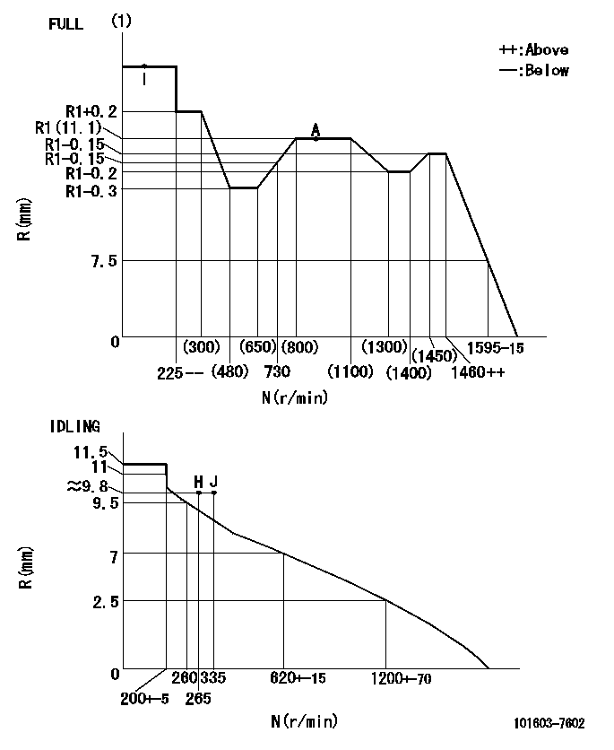
N:Pump speed
R:Rack position (mm)
(1)Torque cam stamping: T1
----------
T1=G16
----------
----------
T1=G16
----------
Speed control lever angle

F:Full speed
I:Idle
(1)Use the pin at R = aa
(2)Stopper bolt set position 'H'
----------
aa=28mm
----------
a=12.5deg+-5deg b=(45deg)+-3deg
----------
aa=28mm
----------
a=12.5deg+-5deg b=(45deg)+-3deg
Stop lever angle
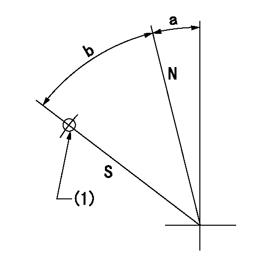
N:Pump normal
S:Stop the pump.
(1)Use the pin at R = aa
----------
aa=45mm
----------
a=12.5deg+-5deg b=40deg+-5deg
----------
aa=45mm
----------
a=12.5deg+-5deg b=40deg+-5deg
0000001501 I/P WITH LOAD PLUNGER ADJ
Plunger assembly number: PL (stamping: ST)
1. Adjustment procedures
(1)Insert the pre-stroke adjusting shims L1 for each cylinder.
(2)Adjust injection quantity.(max. var. bet. cyl. idling a1, full a2)
(3)At basic point A, adjust so that the pre-stroke is L2.
(4)Reconfirm the injection quantity.
----------
PL=131153-4520 ST=A724 L1=1mm L2=4.2+-0.05mm a1=+-14% a2=+-2.5%
----------
----------
PL=131153-4520 ST=A724 L1=1mm L2=4.2+-0.05mm a1=+-14% a2=+-2.5%
----------
Timing setting
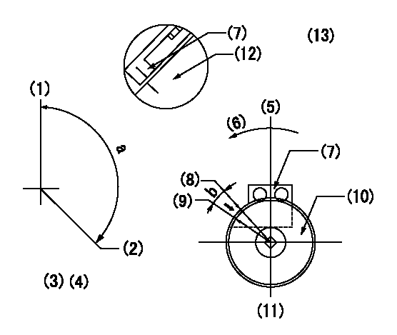
(1)Pump vertical direction
(2)Position of timer's threaded hole at No 1 cylinder's beginning of injection
(3)B.T.D.C.: aa
(4)-
(5)Pump vertical direction
(6)Direction of rotation
(7)Pointer
(8)Pointer stamping
(9)Timing device stamping
(10)Timing device
(11)Move b deg and stamp both at the same time as shown above.
(12)Outside circumference of timing device
(13)Secondary timing stamping position for the No. 1 cylinder's beginning of injection
----------
aa=11deg
----------
a=(150deg) b=1deg
----------
aa=11deg
----------
a=(150deg) b=1deg
Information:
2030-2037, 2039-2042, 2045-2049, 2052-2056, 2058-2061, 2064, 2066-2069, 2072, 2073, 2075- 2077, 2079-2084, 2087-2088, 2090, 2092-2094, 2096, 2097, 2099, 2100, 2103-2109, 2111, 2112, 2114, 2116, 2118, 2119, 2121, 2123-2130, 2132-2136, 2139, 2140, 2142-2146, 2148, 2151, 2152, 2154, 2156, 2157, 2159, 2160, 2164-2166, 2168- 2171, 2173, 2175-2179, 2181-2186, 2188, 2191-2194, 2196, 2197, 2199, 2202-2205, 2207-2209, 2211, 2213, 2215, 2217- 2219, 2221-2228, 2230-2231, 2233-2235, 2237, 2238, 2240, 2242-2245, 2247, 2248, 2250, 2251, 2253-2255, 2258-2261, 2264, 2266-2270, 2272-2283, 2285-2300, 2303-2313, 2315-2317, 2319-2325, 2327, 2328, 2330-2334, 2337, 2339, 2340, 2342- 2346, 2348-2363, 2365, 2370-2372, 2374-2386, 2388-2392, 2395, 2397-2399, 2402, 2404-2408, 2410, 2412, 2413, 2415- 2419, 2421-2429, 2431, 2434-2439, 2441, 2442, 2444, 2446- 2474, 2476-2478, 2480-2485, 2487, 2488, 2490, 2491, 2493- 2498, 2500-2518, 2520-2527, 2530, 2531, 2533-2539, 2542, 2543, 2545, 2547, 2549-2552, 2554, 2557-2565, 2567-2569, 2571-2577, 2579, 2580, 2582, 2584, 2587-2590, 2592-2606, 2608-2614, 2616, 2618, 2619, 2621-2623, 2625-2645, 2647- 2649, 2651, 2653-2655, 2657, 2658, 2660, 2662, 2664, 2666, 2668, 2670-2674, 2676-2679, 2681, 2683, 2685, 2687-2694, 2697-2699, 2701-2704, 2706-2725, 2727-2745, 2747-2767, 2769- 2773, 2775-2779, 2781-2791, 2793, 2794, 2796, 2798-2804, 2806-2812, 2814, 2815, 2817, 2819, 2820, 2822-2826, 2828- 2830, 2832-2839, 2841-2847, 2849-2854, 2856, 2858-2863, 2865-2869, 2871-2873, 2875-2877, 2879, 2881, 2883, 2886- 2888, 2890, 2891, 2893-2898, 2900-2903, 2906-2912, 2914, 2915, 2917, 2918, 2921-2925, 2927-2929, 2931-2934, 2936-2942, 2944-2950, 2952-2955, 2957, 2959, 2962, 2964, 2967-2970, 2973-2975, 2977, 2979, 2983, 2984, 2986, 2989-2991, 2994, 2995, 3004, 3006, 3008, 3010-3014, 3016-3024, 3029-3035, 3037-3039, 3042, 3045, 3047, 3052,
