Information injection-pump assembly
ZEXEL
101603-7580
1016037580
ISUZU
8943968890
8943968890

Rating:
Cross reference number
ZEXEL
101603-7580
1016037580
ISUZU
8943968890
8943968890
Zexel num
Bosch num
Firm num
Name
Calibration Data:
Adjustment conditions
Test oil
1404 Test oil ISO4113 or {SAEJ967d}
1404 Test oil ISO4113 or {SAEJ967d}
Test oil temperature
degC
40
40
45
Nozzle and nozzle holder
105780-8140
Bosch type code
EF8511/9A
Nozzle
105780-0000
Bosch type code
DN12SD12T
Nozzle holder
105780-2080
Bosch type code
EF8511/9
Opening pressure
MPa
17.2
Opening pressure
kgf/cm2
175
Injection pipe
Outer diameter - inner diameter - length (mm) mm 6-2-600
Outer diameter - inner diameter - length (mm) mm 6-2-600
Overflow valve
131424-4920
Overflow valve opening pressure
kPa
127
107
147
Overflow valve opening pressure
kgf/cm2
1.3
1.1
1.5
Tester oil delivery pressure
kPa
157
157
157
Tester oil delivery pressure
kgf/cm2
1.6
1.6
1.6
RED3 control unit part number
407910-2
470
RED3 rack sensor specifications
mm
15
Direction of rotation (viewed from drive side)
Left L
Left L
Injection timing adjustment
Direction of rotation (viewed from drive side)
Left L
Left L
Injection order
1-5-3-6-
2-4
Pre-stroke
mm
4.2
4.15
4.25
Rack position
After adjusting injection quantity. R=A
After adjusting injection quantity. R=A
Beginning of injection position
Governor side NO.1
Governor side NO.1
Difference between angles 1
Cal 1-5 deg. 60 59.5 60.5
Cal 1-5 deg. 60 59.5 60.5
Difference between angles 2
Cal 1-3 deg. 120 119.5 120.5
Cal 1-3 deg. 120 119.5 120.5
Difference between angles 3
Cal 1-6 deg. 180 179.5 180.5
Cal 1-6 deg. 180 179.5 180.5
Difference between angles 4
Cyl.1-2 deg. 240 239.5 240.5
Cyl.1-2 deg. 240 239.5 240.5
Difference between angles 5
Cal 1-4 deg. 300 299.5 300.5
Cal 1-4 deg. 300 299.5 300.5
Injection quantity adjustment
Rack position
(9.3)
Vist
V
2.14
2.14
2.14
Pump speed
r/min
900
900
900
Average injection quantity
mm3/st.
73.5
72.5
74.5
Max. variation between cylinders
%
0
-2.5
2.5
Basic
*
Injection quantity adjustment_02
Rack position
(7.6)
Vist
V
2.5
2.4
2.6
Pump speed
r/min
260
260
260
Average injection quantity
mm3/st.
8.3
7
9.6
Max. variation between cylinders
%
0
-14
14
Governor adjustment
Pump speed
r/min
1210--
Advance angle
deg.
0
0
0
Load
3/4
Remarks
Start
Start
Governor adjustment_02
Pump speed
r/min
1160
Advance angle
deg.
0.3
Load
3/4
Governor adjustment_03
Pump speed
r/min
1500
Advance angle
deg.
5.5
5
6
Load
4/4
Remarks
Finish
Finish
Test data Ex:
Speed control lever angle
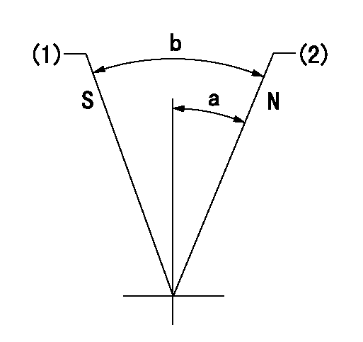
N:Pump normal
S:Stop the pump.
(1)Rack position = aa
(2)Rack position bb
----------
aa=1mm bb=16mm
----------
a=19deg+-5deg b=29deg+-5deg
----------
aa=1mm bb=16mm
----------
a=19deg+-5deg b=29deg+-5deg
0000000901
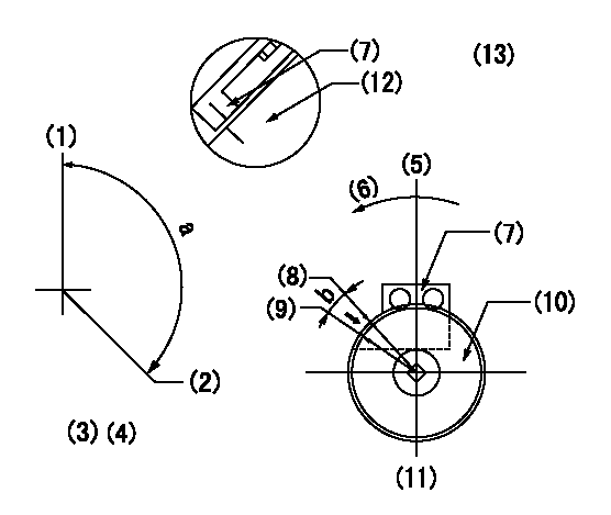
(1)Pump vertical direction
(2)Position of timer's threaded hole at No 1 cylinder's beginning of injection
(3)B.T.D.C.: aa
(4)-
(5)Pump vertical direction
(6)Direction of rotation
(7)Pointer
(8)Pointer stamping
(9)Timing device stamping
(10)Timing device
(11)Move b deg and stamp both at the same time as shown above.
(12)Outside circumference of timing device
(13)Secondary timing stamping position for the No. 1 cylinder's beginning of injection
----------
aa=11deg
----------
a=(150deg) b=1deg
----------
aa=11deg
----------
a=(150deg) b=1deg
Stop lever angle

(Rs) rack sensor specifications
(C/U) control unit part number
(V) Rack sensor output voltage
(R) Rack position (mm)
1. Confirming governor output characteristics (rack 15 mm, span 6 mm)
(1)When the output voltages of the rack sensor are V1 and V2, check that the rack positions R1 and R2 in the table above are satisfied.
----------
----------
----------
----------
Information:
Illustration 9 g06426461
(1) For 323, 330, and 330GC machines use 580-1893 Plate As / For 336GC machines use 581-5268 Plate As
(Q) Bolt and washer
(R) Plate
Install plate assembly (1) using plate (R), bolt, and washer (Q). Tighten the bolts to 55 10 N m (41 7 lb ft). Refer to Illustration 9.
Illustration 10 g06426462
(7) 365-0162 Special Connector
(F) Injector
Install special connector (7) to injector (F). Refer to Illustration 10.
Illustration 11 g06426463
(2) 573-8722 Tank
(8) 3S-2093 Cable Strap
(E) Hose
(M) Harness
Connect hose (E) to tank (2). Refer to Illustration 11.
Illustration 12 g06426465
View of area T
(1) For 323, 330, and 330GC machines use 580-1893 Plate As / For 336GC machines use 581-5268 Plate As
(P) Clip
(S) Bolt and washer
(D1) 45 Degree
Install clip (P) using bolt and washer (S), torque to 28 7 N m (248 62 lb in). Refer to Illustration 12.
Secure the harness (M) using cable strap (8). After tie up, cut all the surplus of strap. Refer to Illustration 11.
Reinstall upper cover (A) and close the upper cover (B). Refer to Illustration 1 and Illustration 2.Replacement Procedure for 336 Excavators
Do not operate or work on this product unless you have read and understood the instruction and warnings in the relevant Operation and Maintenance Manuals and relevant service literature. Failure to follow the instructions or heed the warnings could result in injury or death. Proper care is your responsibility.
Table 3
Required Parts
Item Qty Part Number Part Name
1 1 471-9926 Tank
2 1 581-3324 Plate As
3 1 327-0325 Cable Strap
Illustration 13 g06426466
(A) Upper cover
(B) Upper cover
Remove the upper cover (A) and open the upper cover (B). Refer to Illustration 13.
Illustration 14 g06426467
(C) Tank assembly
(E) Hose
(F) Hose
(G) Strap
Disconnect hose (E) and hose (F) from tank assembly (C). Cut and remove the strap (G). Refer to Illustration 14.
Illustration 15 g06426468
(C) Tank assembly
(H) Bolt and washer
(J) Bolt and washer
(K) Plate assembly
Remove tank assembly (C) by loosening the bolt and washer (H). Refer to Illustration 15.
Remove plate assembly (K) by loosening the bolt and washer (J). Refer to Illustration 15.
Illustration 16 g06426469
(F) Hose
(D1) 10.0 mm (0.4 inch)
Cut and remove the end of hose (F) by 10.0 mm (0.4 inch). Refer to Illustration 16.
Illustration 17 g06426470
(1) 471-9926 Tank
(2) 581-3324 Plate As
(3) 327-0325 Cable Strap
(E) Hose
(H) Bolt and washer
(J) Bolt and washer
(F) Hose
Install the plate assembly (2) and tank (1) using bolt and washer (J) and bolt and washer (H). Refer to Illustration 17.
Connect hose (E) and hose (F) to tank (1). Add cable strap (3) to secure hose. After tie up, cut all the surplus of strap. Refer to Illustration 17.
Reinstall upper cover (A) and close the upper cover (B). Refer to Illustration 13.