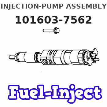
Information injection-pump assembly
ZEXEL
101603-7562
1016037562
ISUZU
1156026912
1156026912
Rating:
Service parts 101603-7562 INJECTION-PUMP ASSEMBLY:
1.
_
7.
COUPLING PLATE
8.
_
9.
_
11.
Nozzle and Holder
1-15300-266-4
12.
Open Pre:MPa(Kqf/cm2)
18.1{185}

15.
NOZZLE SET
Include in #1:
101603-7562
as INJECTION-PUMP ASSEMBLY
Include in #2:
104741-6740
as _
Cross reference number
ZEXEL
101603-7562
1016037562
ISUZU
1156026912
1156026912
Zexel num
Bosch num
Firm num
Name
Calibration Data:
Adjustment conditions
Test oil
1404 Test oil ISO4113 or {SAEJ967d}
1404 Test oil ISO4113 or {SAEJ967d}
Test oil temperature
degC
40
40
45
Nozzle and nozzle holder
105780-8140
Bosch type code
EF8511/9A
Nozzle
105780-0000
Bosch type code
DN12SD12T
Nozzle holder
105780-2080
Bosch type code
EF8511/9
Opening pressure
MPa
17.2
Opening pressure
kgf/cm2
175
Injection pipe
Outer diameter - inner diameter - length (mm) mm 6-2-600
Outer diameter - inner diameter - length (mm) mm 6-2-600
Overflow valve
131424-4920
Overflow valve opening pressure
kPa
127
107
147
Overflow valve opening pressure
kgf/cm2
1.3
1.1
1.5
Tester oil delivery pressure
kPa
157
157
157
Tester oil delivery pressure
kgf/cm2
1.6
1.6
1.6
Direction of rotation (viewed from drive side)
Right R
Right R
Injection timing adjustment
Direction of rotation (viewed from drive side)
Right R
Right R
Injection order
1-5-3-6-
2-4
Pre-stroke
mm
4.9
4.85
4.95
Rack position
After adjusting injection quantity. R=A
After adjusting injection quantity. R=A
Beginning of injection position
Drive side NO.1
Drive side NO.1
Difference between angles 1
Cal 1-5 deg. 60 59.5 60.5
Cal 1-5 deg. 60 59.5 60.5
Difference between angles 2
Cal 1-3 deg. 120 119.5 120.5
Cal 1-3 deg. 120 119.5 120.5
Difference between angles 3
Cal 1-6 deg. 180 179.5 180.5
Cal 1-6 deg. 180 179.5 180.5
Difference between angles 4
Cyl.1-2 deg. 240 239.5 240.5
Cyl.1-2 deg. 240 239.5 240.5
Difference between angles 5
Cal 1-4 deg. 300 299.5 300.5
Cal 1-4 deg. 300 299.5 300.5
Injection quantity adjustment
Adjusting point
-
Rack position
13
Pump speed
r/min
850
850
850
Average injection quantity
mm3/st.
88.8
87.2
90.4
Max. variation between cylinders
%
0
-2.5
2.5
Basic
*
Fixing the rack
*
Standard for adjustment of the maximum variation between cylinders
*
Injection quantity adjustment_02
Adjusting point
H
Rack position
9.5+-0.5
Pump speed
r/min
275
275
275
Average injection quantity
mm3/st.
8
6.7
9.3
Max. variation between cylinders
%
0
-14
14
Fixing the rack
*
Standard for adjustment of the maximum variation between cylinders
*
Injection quantity adjustment_03
Adjusting point
A
Rack position
R1(13)
Pump speed
r/min
850
850
850
Average injection quantity
mm3/st.
88.8
87.8
89.8
Basic
*
Fixing the lever
*
Boost pressure
kPa
30.7
30.7
Boost pressure
mmHg
230
230
Injection quantity adjustment_04
Adjusting point
B
Rack position
R1+0.05
Pump speed
r/min
1400
1400
1400
Average injection quantity
mm3/st.
97
93.8
100.2
Fixing the lever
*
Boost pressure
kPa
30.7
30.7
Boost pressure
mmHg
230
230
Injection quantity adjustment_05
Adjusting point
C
Rack position
R2(R1-0.
5)
Pump speed
r/min
550
550
550
Average injection quantity
mm3/st.
75.2
72
78.4
Fixing the lever
*
Boost pressure
kPa
30.7
30.7
Boost pressure
mmHg
230
230
Injection quantity adjustment_06
Adjusting point
D
Rack position
R2-1.3
Pump speed
r/min
550
550
550
Average injection quantity
mm3/st.
52.5
49.3
55.7
Fixing the lever
*
Boost pressure
kPa
0
0
0
Boost pressure
mmHg
0
0
0
Injection quantity adjustment_07
Adjusting point
I
Rack position
-
Pump speed
r/min
150
150
150
Average injection quantity
mm3/st.
96
96
128
Fixing the lever
*
Boost compensator adjustment
Pump speed
r/min
550
550
550
Rack position
R2-1.3
Boost pressure
kPa
5.3
5.3
8
Boost pressure
mmHg
40
40
60
Boost compensator adjustment_02
Pump speed
r/min
550
550
550
Rack position
R2(R1-0.
5)
Boost pressure
kPa
17.3
17.3
17.3
Boost pressure
mmHg
130
130
130
Timer adjustment
Pump speed
r/min
1200--
Advance angle
deg.
0
0
0
Remarks
Start
Start
Timer adjustment_02
Pump speed
r/min
1150
Advance angle
deg.
0.5
Timer adjustment_03
Pump speed
r/min
1400
Advance angle
deg.
3
2.5
3.5
Remarks
Finish
Finish
Test data Ex:
Governor adjustment
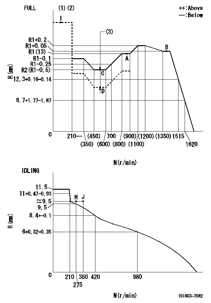
N:Pump speed
R:Rack position (mm)
(1)Torque cam stamping: T1
(2)Tolerance for racks not indicated: +-0.05mm.
(3)Boost compensator stroke: BCL
----------
T1=F37 BCL=1.3+-0.1mm
----------
----------
T1=F37 BCL=1.3+-0.1mm
----------
Speed control lever angle

F:Full speed
I:Idle
(1)Use the hole at R = aa
(2)Stopper bolt set position 'H'
----------
aa=44mm
----------
a=43deg+-5deg b=(38deg)+-3deg
----------
aa=44mm
----------
a=43deg+-5deg b=(38deg)+-3deg
Stop lever angle
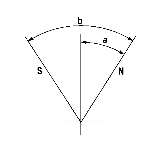
N:Pump normal
S:Stop the pump.
----------
----------
a=25deg+-5deg b=40deg+-5deg
----------
----------
a=25deg+-5deg b=40deg+-5deg
0000001501 RACK SENSOR

V1:Supply voltage
V2f:Full side output voltage
V2i:Idle side output voltage
(A) Black
(B) Yellow
(C) Red
(D) Trimmer
(E): Shaft
(F) Nut
(G) Load lever
1. Load sensor adjustment
(1)Connect as shown in the above diagram and apply supply voltage V1.
(2)Hold the load lever (G) against the full side.
(3)Turn the shaft so that the voltage between (A) and (B) is V2.
(4)Hold the load lever (G) against the idle side.
(5)Adjust (D) so that the voltage between (A) and (B) is V2i.
(6)Repeat the above adjustments.
(7)Tighten the nut (F) at the point satisfying the standards.
(8)Hold the load lever against the full side stopper and the idle side stopper.
(9)At this time, confirm that the full side output voltage is V2f and the idle side output voltage is V2i.
----------
V1=5+-0.02V V2f=0.15+0.03V V2i=2.35-0.03V
----------
----------
V1=5+-0.02V V2f=0.15+0.03V V2i=2.35-0.03V
----------
0000001601 LEVER
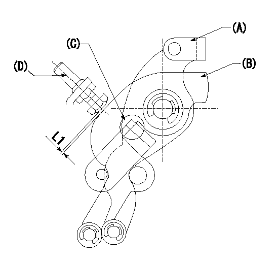
1. Accelerator lever adjustment
(1)Set the speed lever (A) at the idle point H.
(2)Set the control lever where the accelerator lever (B) contacts the speed lever hook (C).
(3)The gap between the accelerator lever (B) and the stopper bolt (D) must be L1.
----------
L1=1+0.5mm
----------
----------
L1=1+0.5mm
----------
0000001701 I/P WITH LOAD PLUNGER ADJ
Plunger assembly number: PL (stamping: ST)
1. Adjustment procedures
(1)Insert the pre-stroke adjusting shims L1 for each cylinder.
(2)Adjust injection quantity.(max. var. bet. cyl. idling a1, full a2)
(3)At basic point A, adjust so that the pre-stroke is L2.
(4)Reconfirm the injection quantity.
----------
PL=131153-5520 ST=A734 L1=1mm L2=4.9+-0.05mm a1=+-14% a2=+-2.5%
----------
----------
PL=131153-5520 ST=A734 L1=1mm L2=4.9+-0.05mm a1=+-14% a2=+-2.5%
----------
Timing setting

(1)Pump vertical direction
(2)Position of timer's threaded hole at No 1 cylinder's beginning of injection
(3)B.T.D.C.: aa
(4)-
----------
aa=11deg
----------
a=(60deg)
----------
aa=11deg
----------
a=(60deg)
Information:
Illustration 6 g06375966
Current hose routing
(E) 3U-2752 Clip
Illustration 7 g06375968
(D3) 32.31 mm (1.272 inch)
(D4) 80.00 mm (3.150 inch)
(1) 178-7023 Boss
Illustration 8 g06375967
New hose routing
(1) 178-7023 Boss
(2) 420-5299 Clip
Remove clip (E) and install boss (1) per the dimensions and secure the hose using two double clips (2), as shown in Illustration 6, Illustration 7, and Illustration 8.Changes to CEM Line Routing for 730C2, 730C2 EJ, 730, and 735 Articulated Trucks
Illustration 9 g06376002
Current hose routing
(F) 421-9627 Bracket As
(G) 3U-2752 Clip
(H) 7K-1181 Cable Strap
Remove bracket assembly (F), clips (G), strap cable (H), and other mounting hardware, as shown in Illustration 9.
Illustration 10 g06376255
New hose routing
(2) 420-5299 Clip
Install two double clips (2) as shown in Illustration 10.Note: The hose routing simplifies the installation and provides additional clearance to the oil gallery on the right-hand side of the machine.Changes to DEF cooling Lines Routing (To/From Tank) for all High Regulated Countries (HRC) Machines
Illustration 11 g06376256
Current hose routing
(J) 312-0288 Clamp
Illustration 12 g06376257
New hose routing
(3) 520-7003 ClampRemove old clamps (J) and replace with the new clamps (3), as shown in Illustration 11 and Illustration 12.Changes to DEF Cooling Lines Routing (To Pump- Both ends) for all HRC Machines
Illustration 13 g06376263
Current clamp
(J) 312-0288 Clamp
Illustration 14 g06376264
New clamp
(3) 520-7003 Clamp
Illustration 15 g06376266
Current clamp
(J) 312-0288 Clamp
Illustration 16 g06376267
New clamp
(3) 520-7003 ClampRemove old clamps (J) and replace with the new clamps (3), as shown in Illustration 13, Illustration 14, Illustration 15, and Illustration 16.Changes to DEF Cooling Lines (From Pump- Both ends) Routing for all HRC Machines
Illustration 17 g06376285
Current clamp
(K) 433-0933 Clamp
Illustration 18 g06376288
New clamp
(4) 520-7002 ClampRemove existing clamps (K) and replace with the new clamps (4), as shown in Illustration 17 and Illustration 18.