Information injection-pump assembly
ZEXEL
101603-7521
1016037521
ISUZU
8943969221
8943969221
Rating:
Cross reference number
ZEXEL
101603-7521
1016037521
ISUZU
8943969221
8943969221
Zexel num
Bosch num
Firm num
Name
Calibration Data:
Adjustment conditions
Test oil
1404 Test oil ISO4113 or {SAEJ967d}
1404 Test oil ISO4113 or {SAEJ967d}
Test oil temperature
degC
40
40
45
Nozzle and nozzle holder
105780-8210
Nozzle
105780-0070
Nozzle holder
105780-2080
Bosch type code
EF8511/9
Opening pressure
MPa
17.2
Opening pressure
kgf/cm2
175
Injection pipe
Outer diameter - inner diameter - length (mm) mm 6-2-600
Outer diameter - inner diameter - length (mm) mm 6-2-600
Overflow valve
131424-4920
Overflow valve opening pressure
kPa
127
107
147
Overflow valve opening pressure
kgf/cm2
1.3
1.1
1.5
Tester oil delivery pressure
kPa
157
157
157
Tester oil delivery pressure
kgf/cm2
1.6
1.6
1.6
Direction of rotation (viewed from drive side)
Left L
Left L
Injection timing adjustment
Direction of rotation (viewed from drive side)
Left L
Left L
Injection order
1-5-3-6-
2-4
Pre-stroke
mm
4.2
4.15
4.25
Rack position
After adjusting injection quantity. R=A
After adjusting injection quantity. R=A
Beginning of injection position
Governor side NO.1
Governor side NO.1
Difference between angles 1
Cal 1-5 deg. 60 59.5 60.5
Cal 1-5 deg. 60 59.5 60.5
Difference between angles 2
Cal 1-3 deg. 120 119.5 120.5
Cal 1-3 deg. 120 119.5 120.5
Difference between angles 3
Cal 1-6 deg. 180 179.5 180.5
Cal 1-6 deg. 180 179.5 180.5
Difference between angles 4
Cyl.1-2 deg. 240 239.5 240.5
Cyl.1-2 deg. 240 239.5 240.5
Difference between angles 5
Cal 1-4 deg. 300 299.5 300.5
Cal 1-4 deg. 300 299.5 300.5
Injection quantity adjustment
Adjusting point
-
Rack position
11.2
Pump speed
r/min
900
900
900
Average injection quantity
mm3/st.
73.5
71.9
75.1
Max. variation between cylinders
%
0
-2.5
2.5
Basic
*
Fixing the rack
*
Standard for adjustment of the maximum variation between cylinders
*
Injection quantity adjustment_02
Adjusting point
H
Rack position
9.5+-0.5
Pump speed
r/min
260
260
260
Average injection quantity
mm3/st.
8.3
7
9.6
Max. variation between cylinders
%
0
-14
14
Fixing the rack
*
Standard for adjustment of the maximum variation between cylinders
*
Injection quantity adjustment_03
Adjusting point
A
Rack position
R1(11.2)
Pump speed
r/min
900
900
900
Average injection quantity
mm3/st.
73.5
72.5
74.5
Basic
*
Fixing the lever
*
Injection quantity adjustment_04
Adjusting point
B
Rack position
R1-0.1
Pump speed
r/min
1500
1500
1500
Average injection quantity
mm3/st.
84.6
80.6
88.6
Fixing the lever
*
Injection quantity adjustment_05
Adjusting point
C
Rack position
R1-0.3
Pump speed
r/min
600
600
600
Average injection quantity
mm3/st.
55.3
52.1
58.5
Fixing the lever
*
Injection quantity adjustment_06
Adjusting point
I
Rack position
-
Pump speed
r/min
150
150
150
Average injection quantity
mm3/st.
103
103
135
Fixing the lever
*
Timer adjustment
Pump speed
r/min
1270--
Advance angle
deg.
0
0
0
Remarks
Start
Start
Timer adjustment_02
Pump speed
r/min
1220
Advance angle
deg.
0.5
Timer adjustment_03
Pump speed
r/min
1500
Advance angle
deg.
5.5
5
6
Remarks
Finish
Finish
Test data Ex:
Governor adjustment
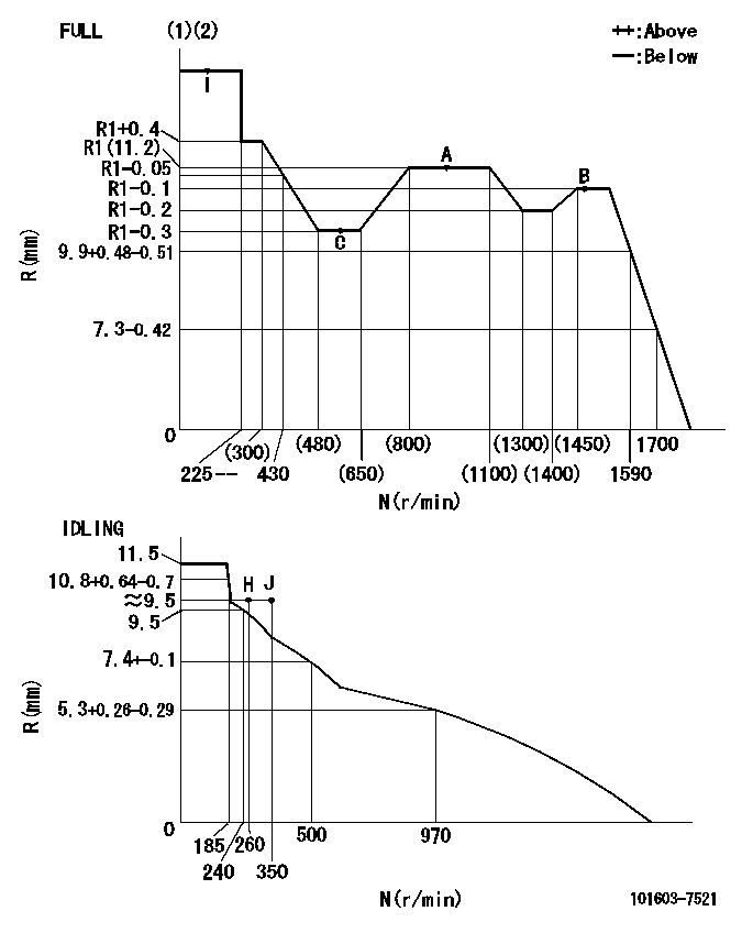
N:Pump speed
R:Rack position (mm)
(1)Torque cam stamping: T1
(2)Tolerance for racks not indicated: +-0.05mm.
----------
T1=F10
----------
----------
T1=F10
----------
Speed control lever angle

F:Full speed
I:Idle
(1)Use the pin at R = aa
(2)Stopper bolt set position 'H'
----------
aa=35mm
----------
a=11deg+-5deg b=(36.5deg)+-3deg
----------
aa=35mm
----------
a=11deg+-5deg b=(36.5deg)+-3deg
Stop lever angle

N:Pump normal
S:Stop the pump.
(1)Use the pin at R = aa
----------
aa=60mm
----------
a=16deg+-5deg b=29deg+-5deg
----------
aa=60mm
----------
a=16deg+-5deg b=29deg+-5deg
0000001501 I/P WITH LOAD PLUNGER ADJ
Plunger assembly number: PL (stamping: ST)
1. Adjustment procedures
(1)Insert the pre-stroke adjusting shims L1 for each cylinder.
(2)Adjust injection quantity.(max. var. bet. cyl. idling a1, full a2)
(3)At basic point A, adjust so that the pre-stroke is L2.
(4)Reconfirm the injection quantity.
----------
PL=131153-4520 ST=A724 L1=1mm L2=4.2+-0.05mm a1=+-14% a2=+-2.5%
----------
----------
PL=131153-4520 ST=A724 L1=1mm L2=4.2+-0.05mm a1=+-14% a2=+-2.5%
----------
Timing setting
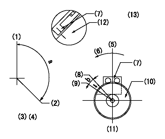
(1)Pump vertical direction
(2)Position of timer's threaded hole at No 1 cylinder's beginning of injection
(3)B.T.D.C.: aa
(4)-
(5)Pump vertical direction
(6)Direction of rotation
(7)Pointer
(8)Pointer stamping
(9)Timing device stamping
(10)Timing device
(11)Move b deg and stamp both at the same time as shown above.
(12)Outside circumference of timing device
(13)Secondary timing stamping position for the No. 1 cylinder's beginning of injection
----------
aa=11deg
----------
a=(150deg) b=1deg
----------
aa=11deg
----------
a=(150deg) b=1deg
Information:
Illustration 4 g01341045
(6) Temperature Sensor
(7) Pressure Sensor
Mount the 271-7350 Warning Indicator Module Gp in a place that is easy to view. Ensure that the ambient temperature is below 45 °C (113 °F), and ensure that the Warning Indicator Module is not directly exposed to high pressure steam cleaning, solvents, the battery off gas, or electrical discharge. Note: The LED display panel may be installed in the cab of the vehicle.
Illustration 5 g01341118
(8) LED display panel
(9) ECM Installation for the Wiring Harness
The 274-7578 Monitor Electronic Control Module is provided with a 307-5521 Wire Harness.
Connect the 70 pin AMP to the ECM using a 160-7690 Connector Plug As. Tighten the Connector Screw for the ECM to 6 1 N m (4 0.73 lb ft).
Locate a 12 VDC or 24 VDC power supply that is always available even when the key is turned "OFF".
Connect the power wires from the wiring harness to the power supply. Install a 15 AMP fuse in this circuit. If an additional wire must be spliced, use a 14 gauge wire.
Attach the appropriate connectors to the pressure sensor, the temperature sensor, and the lamp group. Note: The service tool that is used in this installation is Caterpillar Electronic Technician (CAT ET). The service tool connector is a 9 pin Deutsch connector that contains the CDL (Caterpillar Data Link)/ATA, CAN/J1939, and power. A connection from the 274-7578 Monitor Electronic Control Module to the PC requires a Caterpillar Communications adapter, which connects to the PC via a serial port.The service tool (CAT ET) supports the following functions:
Download and review active alarms and logged alarms
Clear active alarms
View the data in real time.
Flash the diagnostic module.
Provide the capability for the user to configure certain parameters.Software Configuration
Refer to Systems Operation, Troubleshooting, Testing and Adjusting, KENR6695 for a description of controllable parameters and operation instructions.Once the 274-7578 Monitor Electronic Control Modulehas power, the 274-7578 Monitor Electronic Control Module will begin monitoring the pressure sensors and the temperature sensors.
Check whether CAT ET is configured with English or Metric units.
Set CAT ET to Metric units if a Metric unit is not already selected. Specifications
Table 3
System Requirements
Requirements for 12VDC or 24VDC System Value Notes
Operating Voltage Minimum +9V Minimum continuous operating voltage without damage to the ECM
Maximum Operating Voltage +32V Maximum continuous operating voltage without damage to the ECM
The voltage is over the maximum voltage that is allowed (two minutes continuous). +80V At 25 °C (77 °F)
Reverse Voltage (one hour) -32V At 85 °C (185 °F)
Power up voltage for the ECM +9V The minimum voltage for the ECM to internally run. Operating the engine at this voltage will cause the damage to the ECM.
The maximum current draw with key switch off 10mA
Maximum current draw with zero engine speed and no loads being driven 500mA
Maximum continuous operating current draw 10A This highly dependent upon the number and type of loads driven by the ECM
Recommended size for the Battery Fuse. 15A
Table 4
Operating Conditions
Thermal Conditions Vibrations Humidity Tolerance Salt Spray Tolerance Moisture Leakage Chemical Splash Immunity Electrostatic Environment
Operating Temperature Range: