Information injection-pump assembly
BOSCH
9 400 615 189
9400615189
ZEXEL
101603-7510
1016037510
ISUZU
1156026900
1156026900
Rating:
Service parts 101603-7510 INJECTION-PUMP ASSEMBLY:
1.
_
7.
COUPLING PLATE
8.
_
9.
_
11.
Nozzle and Holder
1-15300-161-1
12.
Open Pre:MPa(Kqf/cm2)
22.1{225}
15.
NOZZLE SET
Cross reference number
BOSCH
9 400 615 189
9400615189
ZEXEL
101603-7510
1016037510
ISUZU
1156026900
1156026900
Zexel num
Bosch num
Firm num
Name
101603-7510
9 400 615 189
1156026900 ISUZU
INJECTION-PUMP ASSEMBLY
6SA1-T K 14BF INJECTION PUMP ASSY PE6AD PE
6SA1-T K 14BF INJECTION PUMP ASSY PE6AD PE
Calibration Data:
Adjustment conditions
Test oil
1404 Test oil ISO4113 or {SAEJ967d}
1404 Test oil ISO4113 or {SAEJ967d}
Test oil temperature
degC
40
40
45
Nozzle and nozzle holder
105780-8140
Bosch type code
EF8511/9A
Nozzle
105780-0000
Bosch type code
DN12SD12T
Nozzle holder
105780-2080
Bosch type code
EF8511/9
Opening pressure
MPa
17.2
Opening pressure
kgf/cm2
175
Injection pipe
Outer diameter - inner diameter - length (mm) mm 6-2-600
Outer diameter - inner diameter - length (mm) mm 6-2-600
Overflow valve opening pressure
kPa
157
123
191
Overflow valve opening pressure
kgf/cm2
1.6
1.25
1.95
Tester oil delivery pressure
kPa
157
157
157
Tester oil delivery pressure
kgf/cm2
1.6
1.6
1.6
Direction of rotation (viewed from drive side)
Left L
Left L
Injection timing adjustment
Direction of rotation (viewed from drive side)
Left L
Left L
Injection order
1-5-3-6-
2-4
Pre-stroke
mm
4.7
4.65
4.75
Beginning of injection position
Governor side NO.1
Governor side NO.1
Difference between angles 1
Cal 1-5 deg. 60 59.5 60.5
Cal 1-5 deg. 60 59.5 60.5
Difference between angles 2
Cal 1-3 deg. 120 119.5 120.5
Cal 1-3 deg. 120 119.5 120.5
Difference between angles 3
Cal 1-6 deg. 180 179.5 180.5
Cal 1-6 deg. 180 179.5 180.5
Difference between angles 4
Cyl.1-2 deg. 240 239.5 240.5
Cyl.1-2 deg. 240 239.5 240.5
Difference between angles 5
Cal 1-4 deg. 300 299.5 300.5
Cal 1-4 deg. 300 299.5 300.5
Injection quantity adjustment
Adjusting point
A
Rack position
10.3
Pump speed
r/min
1100
1100
1100
Average injection quantity
mm3/st.
123.6
122.6
124.6
Max. variation between cylinders
%
0
-2.5
2.5
Basic
*
Fixing the lever
*
Injection quantity adjustment_02
Adjusting point
B
Rack position
5.7+-0.5
Pump speed
r/min
425
425
425
Average injection quantity
mm3/st.
9.1
7.1
11.1
Max. variation between cylinders
%
0
-14
14
Fixing the rack
*
Timer adjustment
Pump speed
r/min
850--
Advance angle
deg.
0
0
0
Remarks
Start
Start
Timer adjustment_02
Pump speed
r/min
800
Advance angle
deg.
0.5
Timer adjustment_03
Pump speed
r/min
1120
Advance angle
deg.
1
0.5
1.5
Remarks
Finish
Finish
Test data Ex:
Governor adjustment
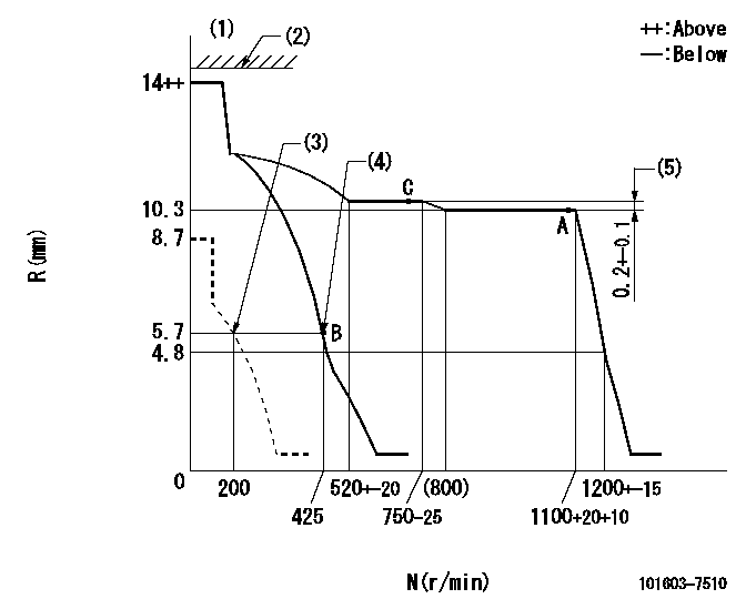
N:Pump speed
R:Rack position (mm)
(1)Target notch: K
(2)RACK LIMIT not operating.
(3)Set idle sub-spring
(4)Main spring setting
(5)Rack difference between N = N1 and N = N2
----------
K=12 N1=1100r/min N2=700r/min
----------
----------
K=12 N1=1100r/min N2=700r/min
----------
Speed control lever angle
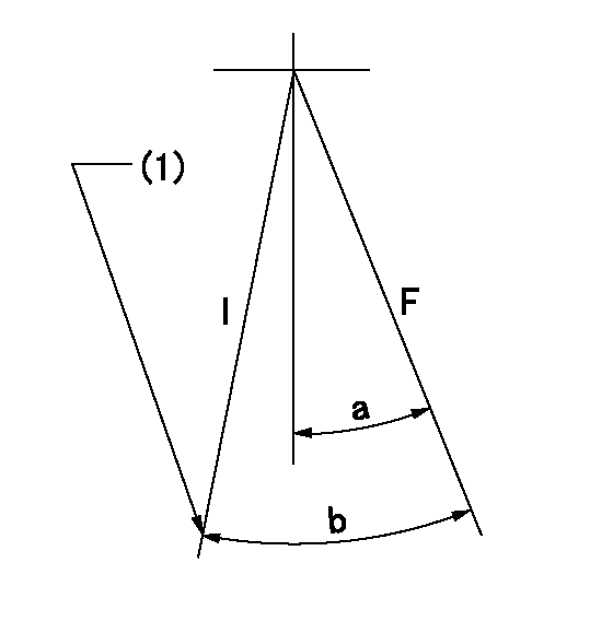
F:Full speed
I:Idle
(1)Stopper bolt setting
----------
----------
a=10deg+-5deg b=25deg+-5deg
----------
----------
a=10deg+-5deg b=25deg+-5deg
Stop lever angle

N:Pump normal
S:Stop the pump.
----------
----------
a=19deg+-5deg b=53deg+-5deg
----------
----------
a=19deg+-5deg b=53deg+-5deg
Timing setting

(1)Pump vertical direction
(2)Position of timer's threaded hole at No 1 cylinder's beginning of injection
(3)B.T.D.C.: aa
(4)-
----------
aa=18deg
----------
a=(40deg)
----------
aa=18deg
----------
a=(40deg)
Information:
Parts Location
Illustration 2 g01631813
(A) Flywheel (B) Fender Group (C) Tank Group (1) 319-8929 Diesel Particulate Filter Gp (2) 329-1696 Tube (3) 329-1701 Tube As (4) 295-3044 Exhaust Support Gp (5) 8T-4223 Hard Washer (6) 8T-4183 Bolt (7) 270-0112 Bellows (8) 7E-3870 Muffler Clamp (9) 247-5011 Pipe Clamp (10) 9Y-8315 Pipe Clamp (11) 8S-5120 Extension Pipe (12) 7S-4994 Rain Cap As (13) 241-6170 Plug (14) 8T-6765 Pipe Plug Installation Procedure
Diesel Particulate Filter Installation
Illustration 3 g01630053
(4) 295-3044 Exhaust Support Gp (Lower half) (5) 8T-4223 Hard Washer (6) 8T-4183 Bolt
Install the lower half of each new 295-3044 Exhaust Support Gp (4) on top of the hood, towards the right side of the cab, by using four new 8T-4183 Bolts (6), and four new 8T-4223 Hard Washers (5). Refer to Illustration 3.
Illustration 4 g01630056
(1) 319-8929 Diesel Particulate Filter Gp
Install the new 319-8929 Diesel Particulate Filter Gp (1) onto the lower half of exhaust support group (4). Refer to Illustration 4.
Illustration 5 g01630074
(4a) Upper half (Exhaust support group) (4b) Bolt (4c) Hard washer (4d) Weld nut
Install the upper half (4a) of exhaust support group by using two bolts (4b), two hard washers (4c), and two weld nuts (4d). Repeat for the other exhaust support group. Refer to Illustration 5.
Illustration 6 g01630094
(2) 329-1696 Tube (3) 329-1701 Tube As (7) 270-0112 Bellows (8) 7E-3870 Muffler Clamp
Install the new 329-1696 Tube (2) to the inlet module tube of the diesel particulate filter group by using one new 7E-3870 Muffler Clamp (8). Refer to Illustration 6.
Install the new 270-0112 Bellows (7) to tube (2) by using one new 7E-3870 Muffler Clamp (8). Refer to Illustration 6.
Install the new 329-1701 Tube Assembly (3) to bellows (7) by using one new 7E-3870 Muffler Clamp (8). Refer to Illustration 6.
Illustration 7 g01630133
(9) 247-5011 Pipe Clamp (11) 8S-5120 Extension Pipe
Install 8S-5120 Extension Pipe (11) to the outlet module tube of the diesel particulate filter group by using a new 247-5011 Pipe Clamp (9). Refer to Illustration 7.
Illustration 8 g01630173
(12) 7S-4994 Rain Cap As
Install the new 7S-4994 Rain Cap Assembly (12) on extension pipe (11). Refer to Illustration 8.
Illustration 9 g01630234
(13) 241-6170 Plug (14) 8T-6765 Pipe Plug
Install a new 241-6170 Plug (13) and a new 8T-6765 Pipe Plug (14) on tube assembly (3) at the respective slots provided. Refer to Illustration 9.
Reconnect the drain lines.Exhaust Monitor Installation
Refer to Special Instruction, REHS5606, "Installation and Operation of the Caterpillar Diesel Particulate Filter (DPF) and the Diagnostic Module for Non-Road Machine Applications (Non-California Applications)" for information regarding the installation and the operation of the exhaust monitor.The exhaust monitor is a device designed to monitor the Caterpillar DPF system continuously. The exhaust monitor provides critical information to the vehicle operator and maintenance
Have questions with 101603-7510?
Group cross 101603-7510 ZEXEL
Isuzu
101603-7510
9 400 615 189
1156026900
INJECTION-PUMP ASSEMBLY
6SA1-T
6SA1-T