Information injection-pump assembly
ZEXEL
101603-7491
1016037491
ISUZU
1156026731
1156026731

Rating:
Cross reference number
ZEXEL
101603-7491
1016037491
ISUZU
1156026731
1156026731
Zexel num
Bosch num
Firm num
Name
Calibration Data:
Adjustment conditions
Test oil
1404 Test oil ISO4113 or {SAEJ967d}
1404 Test oil ISO4113 or {SAEJ967d}
Test oil temperature
degC
40
40
45
Nozzle and nozzle holder
105780-8140
Bosch type code
EF8511/9A
Nozzle
105780-0000
Bosch type code
DN12SD12T
Nozzle holder
105780-2080
Bosch type code
EF8511/9
Opening pressure
MPa
17.2
Opening pressure
kgf/cm2
175
Injection pipe
Outer diameter - inner diameter - length (mm) mm 6-2-600
Outer diameter - inner diameter - length (mm) mm 6-2-600
Overflow valve
131424-4920
Overflow valve opening pressure
kPa
127
107
147
Overflow valve opening pressure
kgf/cm2
1.3
1.1
1.5
Tester oil delivery pressure
kPa
157
157
157
Tester oil delivery pressure
kgf/cm2
1.6
1.6
1.6
Direction of rotation (viewed from drive side)
Right R
Right R
Injection timing adjustment
Direction of rotation (viewed from drive side)
Right R
Right R
Injection order
1-5-3-6-
2-4
Pre-stroke
mm
4.9
4.85
4.95
Rack position
After adjusting injection quantity. R=A
After adjusting injection quantity. R=A
Beginning of injection position
Drive side NO.1
Drive side NO.1
Difference between angles 1
Cal 1-5 deg. 60 59.5 60.5
Cal 1-5 deg. 60 59.5 60.5
Difference between angles 2
Cal 1-3 deg. 120 119.5 120.5
Cal 1-3 deg. 120 119.5 120.5
Difference between angles 3
Cal 1-6 deg. 180 179.5 180.5
Cal 1-6 deg. 180 179.5 180.5
Difference between angles 4
Cyl.1-2 deg. 240 239.5 240.5
Cyl.1-2 deg. 240 239.5 240.5
Difference between angles 5
Cal 1-4 deg. 300 299.5 300.5
Cal 1-4 deg. 300 299.5 300.5
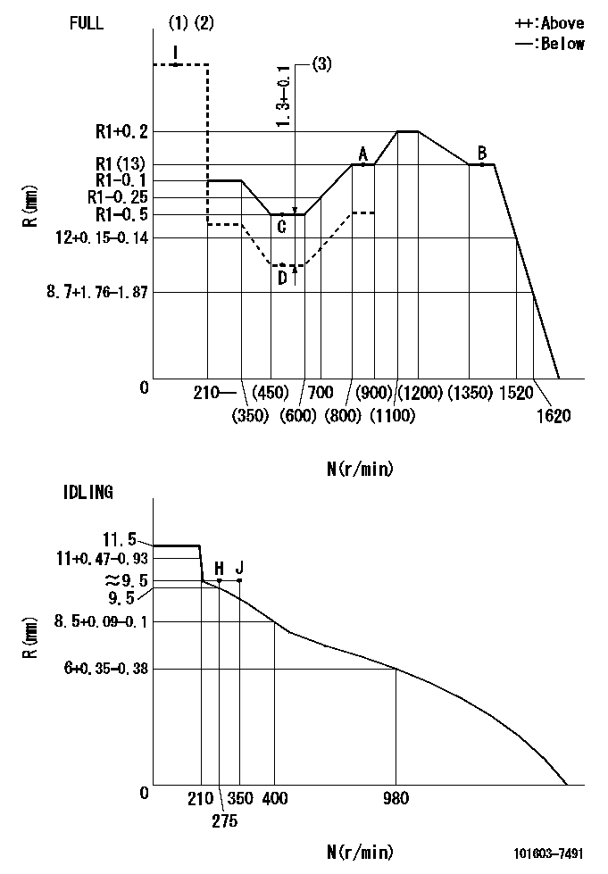
Injection quantity adjustment
Adjusting point
-
Rack position
13
Pump speed
r/min
850
850
850
Average injection quantity
mm3/st.
88.8
87.2
90.4
Max. variation between cylinders
%
0
-2.5
2.5
Basic
*
Fixing the rack
*
Standard for adjustment of the maximum variation between cylinders
*
Injection quantity adjustment_02
Adjusting point
H
Rack position
9.5+-0.5
Pump speed
r/min
275
275
275
Average injection quantity
mm3/st.
8
6.7
9.3
Max. variation between cylinders
%
0
-14
14
Fixing the rack
*
Standard for adjustment of the maximum variation between cylinders
*
Injection quantity adjustment_03
Adjusting point
A
Rack position
R1(13)
Pump speed
r/min
850
850
850
Average injection quantity
mm3/st.
88.8
87.8
89.8
Basic
*
Fixing the lever
*
Boost pressure
kPa
30.7
30.7
Boost pressure
mmHg
230
230
Injection quantity adjustment_04
Adjusting point
B
Rack position
R1(13)
Pump speed
r/min
1400
1400
1400
Average injection quantity
mm3/st.
95.9
92.7
99.1
Fixing the lever
*
Boost pressure
kPa
30.7
30.7
Boost pressure
mmHg
230
230
Injection quantity adjustment_05
Adjusting point
C
Rack position
R2(R1-0.
5)
Pump speed
r/min
550
550
550
Average injection quantity
mm3/st.
75.2
72
78.4
Fixing the lever
*
Boost pressure
kPa
30.7
30.7
Boost pressure
mmHg
230
230
Injection quantity adjustment_06
Adjusting point
D
Rack position
R2-1.3
Pump speed
r/min
550
550
550
Average injection quantity
mm3/st.
52.5
49.3
55.7
Fixing the lever
*
Boost pressure
kPa
0
0
0
Boost pressure
mmHg
0
0
0
Injection quantity adjustment_07
Adjusting point
I
Rack position
-
Pump speed
r/min
150
150
150
Average injection quantity
mm3/st.
96
96
128
Fixing the lever
*
Boost compensator adjustment
Pump speed
r/min
550
550
550
Rack position
R2-1.3
Boost pressure
kPa
5.3
5.3
8
Boost pressure
mmHg
40
40
60
Boost compensator adjustment_02
Pump speed
r/min
550
550
550
Rack position
R2(R1-0.
5)
Boost pressure
kPa
17.3
17.3
17.3
Boost pressure
mmHg
130
130
130
Timer adjustment
Pump speed
r/min
1200--
Advance angle
deg.
0
0
0
Remarks
Start
Start
Timer adjustment_02
Pump speed
r/min
1150
Advance angle
deg.
0.5
Timer adjustment_03
Pump speed
r/min
1400
Advance angle
deg.
3
2.5
3.5
Remarks
Finish
Finish
Test data Ex:
Governor adjustment
N:Pump speed
R:Rack position (mm)
(1)Torque cam stamping: T1
(2)Tolerance for racks not indicated: +-0.05mm.
(3)Boost compensator stroke
----------
T1=F20
----------
----------
T1=F20
----------
Speed control lever angle
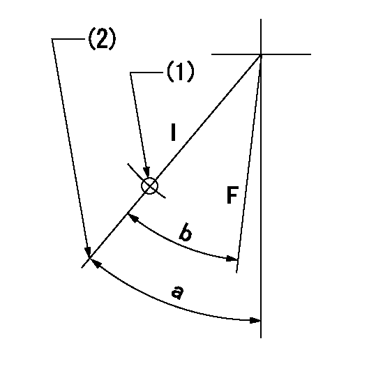
F:Full speed
I:Idle
(1)Use the hole at R = aa
(2)Stopper bolt set position 'H'
----------
aa=35mm
----------
a=43deg+-5deg b=39deg+-3deg
----------
aa=35mm
----------
a=43deg+-5deg b=39deg+-3deg
Stop lever angle

N:Pump normal
S:Stop the pump.
----------
----------
a=25deg+-5deg b=40deg+-5deg
----------
----------
a=25deg+-5deg b=40deg+-5deg
0000001501 I/P WITH LOAD PLUNGER ADJ
Plunger assembly number: PL (stamping: ST)
1. Adjustment procedures
(1)Insert the pre-stroke adjusting shims L1 for each cylinder.
(2)Adjust injection quantity.(max. var. bet. cyl. idling a1, full a2)
(3)At basic point A, adjust so that the pre-stroke is L2.
(4)Reconfirm the injection quantity.
----------
PL=131153-5520 ST=A734 L1=1mm L2=4.9+-0.05mm a1=+-14% a2=+-2.5%
----------
----------
PL=131153-5520 ST=A734 L1=1mm L2=4.9+-0.05mm a1=+-14% a2=+-2.5%
----------
Timing setting

(1)Pump vertical direction
(2)Position of timer's threaded hole at No 1 cylinder's beginning of injection
(3)B.T.D.C.: aa
(4)-
----------
aa=11deg
----------
a=(60deg)
----------
aa=11deg
----------
a=(60deg)
Information:
Table 1
Required Parts
Callout Part Number Description Qty
1 7E-3870 Muffler Clamp 1
2 309-3554 Diesel Particulate Filter Group 1
3 309-3592 Clamp Assembly 1
4 309-3864 Tube 1
5 122-4026 Spacer 4
6 7X-0605 Hard Washer 6
7 8T-4244 Nut 2
8 8T-4910 Bolt 4
9 271-6537 Exhaust Monitor Group 1
10 216-7990 Installation Assembly 1
11 282-0031 Remote Display 1
12 220-3778 Adapter Cable Assembly (INTERFACE) 1 Parts Location
Illustration 2 g01549193
(1) 7E-3870 Muffler Clamp (2) 309-3554 Diesel Particulate Filter Group (3) 309-3592 Clamp Assembly (4) 309-3864 Tube (5) 122-4026 Spacer (6) 7X-0605 Hard Washer (7) 8T-4244 Nut (8) 8T-4910 Bolt Installation Procedure
You must read and thoroughly understand the guidelines in Special Instruction, REHS1807, "Installation Guide for Particulate Trap Exhaust Filters" before you attempt any part of the following installation procedure.The installation procedure that follows is specific for the listed machines.Diesel Particulate Filter Installation
Remove the existing muffler.
Illustration 3 g01457287
(A) Flared end (1) 7E-3870 Muffler Clamp (4) 309-3864 Tube
Install 309-3864 Tube (4) by attaching flared end (A) to the turbocharger. Leave 7E-3870 Muffler Clamp (1) loosely attached on the other end of tube (4) .
Illustration 4 g01457295
(3) 309-3592 Clamp Assembly (Lower half) (5) 122-4026 Spacer (6) 7X-0605 Hard Washer (8) 8T-4910 Bolt
Remove the two bolts, two hard washers, two lock washers, and two nuts from 309-3592 Clamp Assembly (3). Keep these parts together with the upper half of the clamp assembly. These parts will be reinstalled in Step 8.
Install the lower half of 309-3592 Clamp Assembly (3) to the existing bracket near the turbocharger by using two 8T-4910 Bolts (8), two 7X-0605 Hard Washers (6), and two 122-4026 Spacers (5). Refer to Illustration 4.
Illustration 5 g01457434
(1) 7E-3870 Muffler Clamp (2) 309-3554 Diesel Particulate Filter Group (4) 309-3864 Tube (5) 122-4026 Spacer (6) 7X-0605 Hard Washer (7) 8T-4244 Nut (8) 8T-4910 Bolt
Install 309-3554 Diesel Particulate Filter Group (2) by inserting the inlet tube of the diesel particulate filter over 309-3864 Tube (4). The weight of the diesel particulate filter group is approximately 40 kg (88 lb).
Secure the diesel particulate filter to the other bracket on the engine block by using two 8T-4910 Bolts (8), two 8T-4244 Nuts (7), two 122-4026 Spacers (5), and four 7X-0605 Hard Washers (6) .
Tighten 7E-3870 Muffler Clamp (1) over the inlet tube of the diesel particulate filter