Information injection-pump assembly
ZEXEL
101603-7451
1016037451
ISUZU
1156026532
1156026532
Rating:
Cross reference number
ZEXEL
101603-7451
1016037451
ISUZU
1156026532
1156026532
Zexel num
Bosch num
Firm num
Name
Calibration Data:
Adjustment conditions
Test oil
1404 Test oil ISO4113 or {SAEJ967d}
1404 Test oil ISO4113 or {SAEJ967d}
Test oil temperature
degC
40
40
45
Nozzle and nozzle holder
105780-8140
Bosch type code
EF8511/9A
Nozzle
105780-0000
Bosch type code
DN12SD12T
Nozzle holder
105780-2080
Bosch type code
EF8511/9
Opening pressure
MPa
17.2
Opening pressure
kgf/cm2
175
Injection pipe
Outer diameter - inner diameter - length (mm) mm 6-2-600
Outer diameter - inner diameter - length (mm) mm 6-2-600
Overflow valve
131424-4920
Overflow valve opening pressure
kPa
127
107
147
Overflow valve opening pressure
kgf/cm2
1.3
1.1
1.5
Tester oil delivery pressure
kPa
157
157
157
Tester oil delivery pressure
kgf/cm2
1.6
1.6
1.6
Direction of rotation (viewed from drive side)
Right R
Right R
Injection timing adjustment
Direction of rotation (viewed from drive side)
Right R
Right R
Injection order
1-5-3-6-
2-4
Pre-stroke
mm
3.6
3.55
3.65
Rack position
After adjusting injection quantity. R=A
After adjusting injection quantity. R=A
Beginning of injection position
Drive side NO.1
Drive side NO.1
Difference between angles 1
Cal 1-5 deg. 60 59.5 60.5
Cal 1-5 deg. 60 59.5 60.5
Difference between angles 2
Cal 1-3 deg. 120 119.5 120.5
Cal 1-3 deg. 120 119.5 120.5
Difference between angles 3
Cal 1-6 deg. 180 179.5 180.5
Cal 1-6 deg. 180 179.5 180.5
Difference between angles 4
Cyl.1-2 deg. 240 239.5 240.5
Cyl.1-2 deg. 240 239.5 240.5
Difference between angles 5
Cal 1-4 deg. 300 299.5 300.5
Cal 1-4 deg. 300 299.5 300.5
Injection quantity adjustment
Adjusting point
-
Rack position
13.3
Pump speed
r/min
850
850
850
Average injection quantity
mm3/st.
98.6
97
100.2
Max. variation between cylinders
%
0
-2.5
2.5
Basic
*
Fixing the rack
*
Standard for adjustment of the maximum variation between cylinders
*
Injection quantity adjustment_02
Adjusting point
H
Rack position
9.5+-0.5
Pump speed
r/min
275
275
275
Average injection quantity
mm3/st.
8
6.7
9.3
Max. variation between cylinders
%
0
-14
14
Fixing the rack
*
Standard for adjustment of the maximum variation between cylinders
*
Injection quantity adjustment_03
Adjusting point
A
Rack position
R1(13.3)
Pump speed
r/min
850
850
850
Average injection quantity
mm3/st.
98.6
97.6
99.6
Basic
*
Fixing the lever
*
Boost pressure
kPa
33.3
33.3
Boost pressure
mmHg
250
250
Injection quantity adjustment_04
Adjusting point
B
Rack position
R1-0.15
Pump speed
r/min
1400
1400
1400
Average injection quantity
mm3/st.
98.6
95.4
101.8
Fixing the lever
*
Boost pressure
kPa
33.3
33.3
Boost pressure
mmHg
250
250
Injection quantity adjustment_05
Adjusting point
C
Rack position
R2(R1-0.
55)
Pump speed
r/min
550
550
550
Average injection quantity
mm3/st.
78.6
75.4
81.8
Fixing the lever
*
Boost pressure
kPa
33.3
33.3
Boost pressure
mmHg
250
250
Injection quantity adjustment_06
Adjusting point
D
Rack position
R2-1.35
Pump speed
r/min
550
550
550
Average injection quantity
mm3/st.
54
50.8
57.2
Fixing the lever
*
Boost pressure
kPa
0
0
0
Boost pressure
mmHg
0
0
0
Injection quantity adjustment_07
Adjusting point
I
Rack position
-
Pump speed
r/min
150
150
150
Average injection quantity
mm3/st.
93
93
125
Fixing the lever
*
Boost compensator adjustment
Pump speed
r/min
550
550
550
Rack position
R2-1.35
Boost pressure
kPa
3.3
3.3
6
Boost pressure
mmHg
25
25
45
Boost compensator adjustment_02
Pump speed
r/min
550
550
550
Rack position
R2(R1-0.
55)
Boost pressure
kPa
20
20
20
Boost pressure
mmHg
150
150
150
Timer adjustment
Pump speed
r/min
(1170)
Advance angle
deg.
0
0
0
Remarks
Start
Start
Timer adjustment_02
Pump speed
r/min
1325
Advance angle
deg.
1.5
1
2
Timer adjustment_03
Pump speed
r/min
1400
Advance angle
deg.
2
1.5
2.5
Remarks
Finish
Finish
Test data Ex:
Governor adjustment
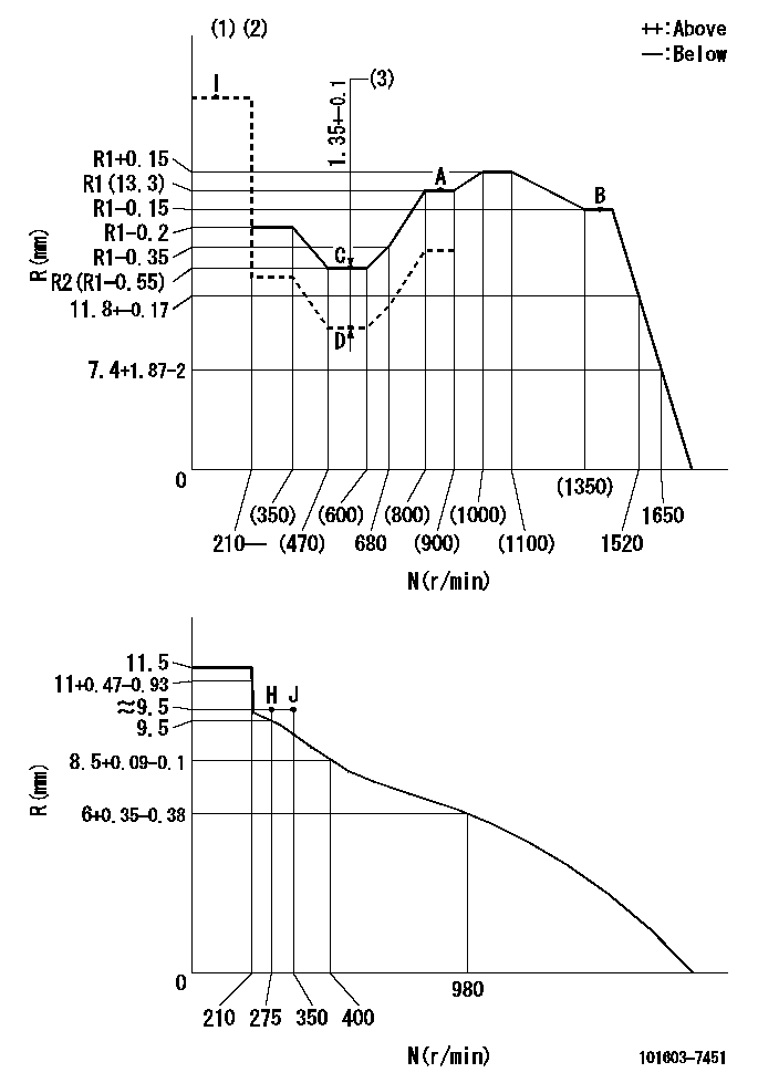
N:Pump speed
R:Rack position (mm)
(1)Torque cam stamping: T1
(2)Tolerance for racks not indicated: +-0.05mm.
(3)Boost compensator stroke
----------
T1=F19
----------
----------
T1=F19
----------
Speed control lever angle

F:Full speed
I:Idle
(1)Use the hole at R = aa
(2)Stopper bolt set position 'H'
----------
aa=48mm
----------
a=43deg+-5deg b=(37deg)+-3deg
----------
aa=48mm
----------
a=43deg+-5deg b=(37deg)+-3deg
Stop lever angle

N:Pump normal
S:Stop the pump.
----------
----------
a=25deg+-5deg b=40deg+-5deg
----------
----------
a=25deg+-5deg b=40deg+-5deg
0000001501 RACK SENSOR

V1:Supply voltage
V2f:Full side output voltage
V2i:Idle side output voltage
(A) Black
(B) Yellow
(C) Red
(D) Trimmer
(E): Shaft
(F) Nut
(G) Load lever
1. Load sensor adjustment
(1)Connect as shown in the above diagram and apply supply voltage V1.
(2)Hold the load lever (G) against the full side.
(3)Turn the shaft so that the voltage between (A) and (B) is V2.
(4)Hold the load lever (G) against the idle side.
(5)Adjust (D) so that the voltage between (A) and (B) is V2i.
(6)Repeat the above adjustments.
(7)Tighten the nut (F) at the point satisfying the standards.
(8)Hold the load lever against the full side stopper and the idle side stopper.
(9)At this time, confirm that the full side output voltage is V2f and the idle side output voltage is V2i.
----------
V1=5+-0.02V V2f=0.15+0.03V V2i=2.35-0.03V
----------
----------
V1=5+-0.02V V2f=0.15+0.03V V2i=2.35-0.03V
----------
0000001601 I/P WITH LOAD PLUNGER ADJ
Plunger assembly number: PL (stamping: ST)
1. Adjustment procedures
(1)Insert the pre-stroke adjusting shims L1 for each cylinder.
(2)Adjust injection quantity.(max. var. bet. cyl. idling a1, full a2)
(3)At basic point A, adjust so that the pre-stroke is L2.
(4)Reconfirm the injection quantity.
----------
PL=131153-3720 ST=A716 L1=1mm L2=3.6+-0.05mm a1=+-14% a2=+-2.5%
----------
----------
PL=131153-3720 ST=A716 L1=1mm L2=3.6+-0.05mm a1=+-14% a2=+-2.5%
----------
Timing setting

(1)Pump vertical direction
(2)Position of timer's threaded hole at No 1 cylinder's beginning of injection
(3)B.T.D.C.: aa
(4)-
----------
aa=10deg
----------
a=(60deg)
----------
aa=10deg
----------
a=(60deg)
Information:
(1) Torque for bushing ... 150 10 lb. ft.(20.7 1.4 mkg)(2) Thickness of spacers: 5M2697 Spacer ... .170 in.(4.32 mm)2M4208 Spacer ... .174 in.(4.42 mm)2M4209 Spacer ... .178 in.(4.52 mm)2M4210 Spacer ... .182 in.(4.62 mm)2M4211 Spacer ... .186 in.(4.72 mm)2M4212 Spacer ... .190 in.(4.82 mm)5M2691 Spacer ... .194 in.(4.93 mm)5S7189 Spacer ... .198 in.(5.03 mm)(3) 1S7590 Spring: Length under test force ... 1.522 in.(38.66 mm)Test force ... 22.6 1.1 lbs.(10.25 5 kg)Free length after test ... 1.751 in.(44.47 mm)Outside diameter ... .995 in.(25.27 mm)(4) Timing dimension for the fuel injection pumps: On engine with 8S7167 Gauge (A) ... 4.355 .002 in.(110.62 0.05 mm)Off engine with 8S7167 Gauge (A) ... 4.392 .002 in.(11.56 0.05 mm)(5) Length of pump plunger ... 2.7212 .0015 in.(69.118 0.038 mm) Minimum permissible length ... 2.7147 in.(68.953 mm)(6) Bore in the bearings for the rack: Bearing at the rear (later) ... .5020 .0015 in.(12.751 0.038 mm)Bearing at the front (later) ... .5023 .0015 in.(12.758 0.038 mm)Both bearings (earlier) ... .5010 .0003 in.(12.725 0.008 mm)Diameter of fuel rack ... .4983 to .4987 in.(12.656 to 12.666 mm)Maximum permissible clearance between rack and bearings ... .005 in.(0.13 mm)(7) Bore in bearings for the camshaft ... 2.1245 to 2.1255 in.(53.962 to 53.987 mm) Diameter of bearing journals of the camshaft ... 2.1215 to 2.1225 in.(53.886 to 53.911 mm)Maximum permissible clearance between the bearings and the camshaft journals ... .010 in.(0.25 mm) (8) Torque for the nuts that hold the fuel lines ... 30 5 lb. ft.(4.1 0.7 mkg)(9) Torque for the nuts that hold the nozzles ... 55 5 lb. ft.(7.6 0.7 mkg)(10) Body(11) Tighten nozzle finger tight in body.(12) Torque for glow plug ... 120 24 lb. in.(138.4 27.6 cm.kg)(13) Torque for precombustion chamber ... 150 10 lb. ft.(20.7 1.4 mkg)