Information injection-pump assembly
ZEXEL
101603-7430
1016037430
ISUZU
8943961610
8943961610

Rating:
Cross reference number
ZEXEL
101603-7430
1016037430
ISUZU
8943961610
8943961610
Zexel num
Bosch num
Firm num
Name
Calibration Data:
Adjustment conditions
Test oil
1404 Test oil ISO4113 or {SAEJ967d}
1404 Test oil ISO4113 or {SAEJ967d}
Test oil temperature
degC
40
40
45
Nozzle and nozzle holder
105780-8210
Nozzle
105780-0070
Bosch type code
DN12SD12T-1
Nozzle holder
105780-2080
Bosch type code
EF8511/9
Opening pressure
MPa
17.2
Opening pressure
kgf/cm2
175
Injection pipe
Outer diameter - inner diameter - length (mm) mm 6-2-600
Outer diameter - inner diameter - length (mm) mm 6-2-600
Overflow valve
131424-4920
Overflow valve opening pressure
kPa
127
107
147
Overflow valve opening pressure
kgf/cm2
1.3
1.1
1.5
Tester oil delivery pressure
kPa
157
157
157
Tester oil delivery pressure
kgf/cm2
1.6
1.6
1.6
Direction of rotation (viewed from drive side)
Left L
Left L
Injection timing adjustment
Direction of rotation (viewed from drive side)
Left L
Left L
Injection order
1-5-3-6-
2-4
Pre-stroke
mm
4.2
4.15
4.25
Rack position
After adjusting injection quantity. R=A
After adjusting injection quantity. R=A
Beginning of injection position
Governor side NO.1
Governor side NO.1
Difference between angles 1
Cal 1-5 deg. 60 59.5 60.5
Cal 1-5 deg. 60 59.5 60.5
Difference between angles 2
Cal 1-3 deg. 120 119.5 120.5
Cal 1-3 deg. 120 119.5 120.5
Difference between angles 3
Cal 1-6 deg. 180 179.5 180.5
Cal 1-6 deg. 180 179.5 180.5
Difference between angles 4
Cyl.1-2 deg. 240 239.5 240.5
Cyl.1-2 deg. 240 239.5 240.5
Difference between angles 5
Cal 1-4 deg. 300 299.5 300.5
Cal 1-4 deg. 300 299.5 300.5
Injection quantity adjustment
Adjusting point
-
Rack position
11.2
Pump speed
r/min
900
900
900
Average injection quantity
mm3/st.
73.5
71.9
75.1
Max. variation between cylinders
%
0
-2.5
2.5
Basic
*
Fixing the rack
*
Standard for adjustment of the maximum variation between cylinders
*
Injection quantity adjustment_02
Adjusting point
H
Rack position
9.5+-0.5
Pump speed
r/min
260
260
260
Average injection quantity
mm3/st.
8.3
7
9.6
Max. variation between cylinders
%
0
-14
14
Fixing the rack
*
Standard for adjustment of the maximum variation between cylinders
*
Injection quantity adjustment_03
Adjusting point
A
Rack position
R1(11.2)
Pump speed
r/min
900
900
900
Average injection quantity
mm3/st.
73.5
72.5
74.5
Basic
*
Fixing the lever
*
Injection quantity adjustment_04
Adjusting point
B
Rack position
R1-0.1
Pump speed
r/min
1500
1500
1500
Average injection quantity
mm3/st.
84.6
80.6
88.6
Fixing the lever
*
Injection quantity adjustment_05
Adjusting point
C
Rack position
R1-0.3
Pump speed
r/min
600
600
600
Average injection quantity
mm3/st.
55.3
52.1
58.5
Fixing the lever
*
Injection quantity adjustment_06
Adjusting point
I
Rack position
-
Pump speed
r/min
150
150
150
Average injection quantity
mm3/st.
103
103
135
Fixing the lever
*
Timer adjustment
Pump speed
r/min
1210--
Advance angle
deg.
0
0
0
Load
3/4
Remarks
Start
Start
Timer adjustment_02
Pump speed
r/min
1160
Advance angle
deg.
0.3
Load
3/4
Timer adjustment_03
Pump speed
r/min
1500
Advance angle
deg.
5.5
5
6
Load
4/4
Remarks
Finish
Finish
Test data Ex:
Governor adjustment
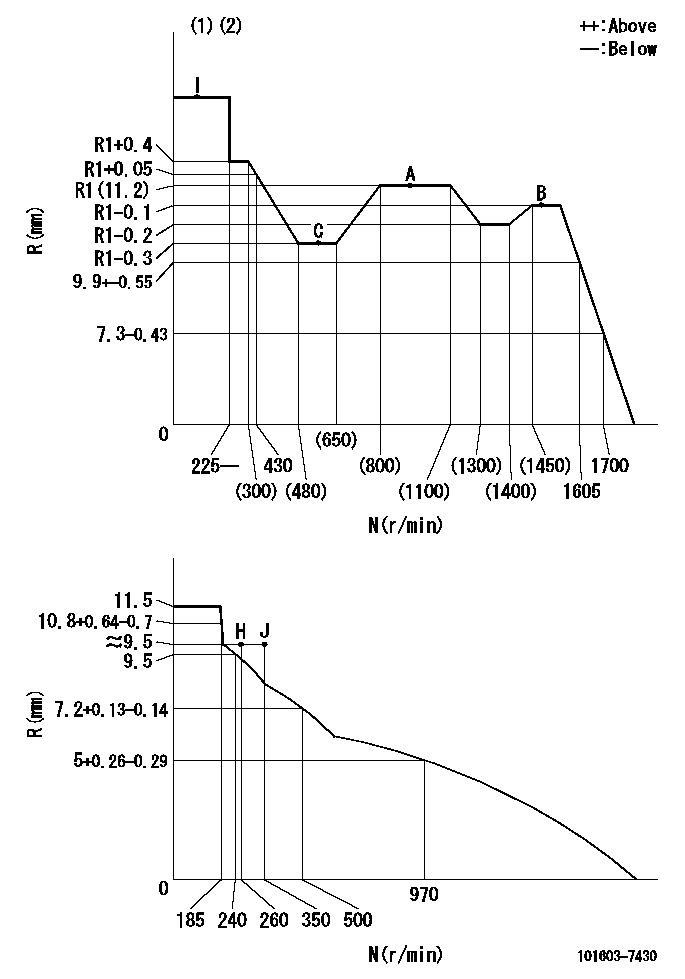
N:Pump speed
R:Rack position (mm)
(1)Torque cam stamping: T1
(2)Tolerance for racks not indicated: +-0.05mm.
----------
T1=E76
----------
----------
T1=E76
----------
Speed control lever angle
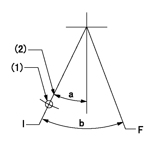
F:Full speed
I:Idle
(1)Use the hole at R = aa
(2)Stopper bolt set position 'H'
----------
aa=60mm
----------
a=28.5deg+-5deg b=(38deg)+-3deg
----------
aa=60mm
----------
a=28.5deg+-5deg b=(38deg)+-3deg
Stop lever angle
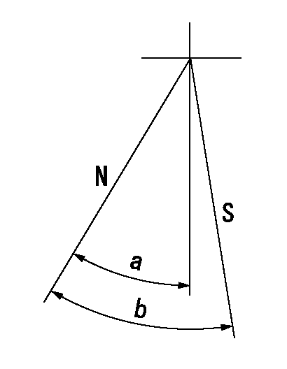
N:Pump normal
S:Stop the pump.
----------
----------
a=32.5deg+-5deg b=40deg+-5deg
----------
----------
a=32.5deg+-5deg b=40deg+-5deg
0000001501 I/P WITH LOAD PLUNGER ADJ
Plunger assembly number: PL (stamping: ST)
1. Adjustment procedures
(1)Insert the pre-stroke adjusting shims L1 for each cylinder.
(2)Adjust injection quantity.(max. var. bet. cyl. idling a1, full a2)
(3)At basic point A, adjust so that the pre-stroke is L2.
(4)Reconfirm the injection quantity.
----------
PL=131153-4520 ST=A724 L1=1mm L2=4.2+-0.05mm a1=+-14% a2=+-2.5%
----------
----------
PL=131153-4520 ST=A724 L1=1mm L2=4.2+-0.05mm a1=+-14% a2=+-2.5%
----------
Timing setting

(1)Pump vertical direction
(2)Position of timer's threaded hole at No 1 cylinder's beginning of injection
(3)B.T.D.C.: aa
(4)-
----------
aa=10deg
----------
a=(150deg)
----------
aa=10deg
----------
a=(150deg)
Information:
1. Remove the retaining ring (1) and pin (2). 2. Remove the seat (3), bolt (4), washers (5), and spring (6).3. Remove the sleeve and bearing assembly from the cylinder and weight assembly. 4. Remove the retaining ring (7) from sleeve (8).5. Remove the bearing (9) and races (10) from sleeve (8). 6. Remove the valve (11) from piston (12).7. Remove the retaining ring (13) from the cylinder and weight assembly.8. Remove the weight assembly (14).9. Remove piston (12) and sleeve (15) from the cylinder (16).10. Remove the O-ring seal from sleeve (15). 11. Remove the speed limiter plug (17), spring (18), and plunger (19) from the governor housing.12. Remove the high idle screw (21) and low idle screw (20). 13. Remove the bolt and lock that holds the shaft (22) to lever assembly (23).14. Remove the shaft (22) and lever assembly (23) from governor housing.15. Remove the seal and bearings from governor housing. 16. Remove the two bolts (25) and lock. Remove the lever (24) and shaft (26) from idle screw housing.17. Remove the two seals and bearing from idle screw housing.Assemble Governor
1. Install the O-ring seal (3) on sleeve (4).2. Install piston (2) and sleeve (4) in the cylinder (1). 3. Put the weight assembly (6) in position on cylinder (1), and install retaining ring (5). 4. Install valve (8) in piston (2).5. Install the bearing and races in sleeve. Install the retaining ring. Install the sleeve and bearing assembly (7) on valve (8). 6. Put the bolt (10), washers (11), and spring (12) in position in seat (9). 7. Put the holes in seat (9), sleeve and bearing assembly (7), and valve (8) in alignment, and install the pin (13). Install the retaining ring (14). 8. Use tool setup (A) to install the inner seal in idle screw housing with the spring side of seal toward tool setup (A). Use tool setup (A) to install the outer seal in housing with lip of seal toward inside of housing. Put clean oil on the bearing and lip of seals.9. Put the shaft and lever in position in the idle screw housing, and install the bolts and lock. 10. Install the two bearings in governor housing. Use tool setup (A) to install the seal in housing with lip of seal toward inside of the governor housing. Put clean oil on the bearings and lip of seal. 11. Put the shaft (15) and lever assembly (17) in position in governor housing, and install the bolt (16) and lock. Install the high and low idle screws in housing. Install the speed limiter plunger, spring, and plug in housing.end by: a) connection of governor to fuel injection pump housing
1. Install the O-ring seal (3) on sleeve (4).2. Install piston (2) and sleeve (4) in the cylinder (1). 3. Put the weight assembly (6) in position on cylinder (1), and install retaining ring (5). 4. Install valve (8) in piston (2).5. Install the bearing and races in sleeve. Install the retaining ring. Install the sleeve and bearing assembly (7) on valve (8). 6. Put the bolt (10), washers (11), and spring (12) in position in seat (9). 7. Put the holes in seat (9), sleeve and bearing assembly (7), and valve (8) in alignment, and install the pin (13). Install the retaining ring (14). 8. Use tool setup (A) to install the inner seal in idle screw housing with the spring side of seal toward tool setup (A). Use tool setup (A) to install the outer seal in housing with lip of seal toward inside of housing. Put clean oil on the bearing and lip of seals.9. Put the shaft and lever in position in the idle screw housing, and install the bolts and lock. 10. Install the two bearings in governor housing. Use tool setup (A) to install the seal in housing with lip of seal toward inside of the governor housing. Put clean oil on the bearings and lip of seal. 11. Put the shaft (15) and lever assembly (17) in position in governor housing, and install the bolt (16) and lock. Install the high and low idle screws in housing. Install the speed limiter plunger, spring, and plug in housing.end by: a) connection of governor to fuel injection pump housing