Information injection-pump assembly
ZEXEL
101603-7424
1016037424
ISUZU
8943968751
8943968751

Rating:
Cross reference number
ZEXEL
101603-7424
1016037424
ISUZU
8943968751
8943968751
Zexel num
Bosch num
Firm num
Name
Calibration Data:
Adjustment conditions
Test oil
1404 Test oil ISO4113 or {SAEJ967d}
1404 Test oil ISO4113 or {SAEJ967d}
Test oil temperature
degC
40
40
45
Nozzle and nozzle holder
105780-8210
Nozzle
105780-0070
Nozzle holder
105780-2080
Bosch type code
EF8511/9
Opening pressure
MPa
17.2
Opening pressure
kgf/cm2
175
Injection pipe
Outer diameter - inner diameter - length (mm) mm 6-2-600
Outer diameter - inner diameter - length (mm) mm 6-2-600
Overflow valve
131424-4920
Overflow valve opening pressure
kPa
127
107
147
Overflow valve opening pressure
kgf/cm2
1.3
1.1
1.5
Tester oil delivery pressure
kPa
157
157
157
Tester oil delivery pressure
kgf/cm2
1.6
1.6
1.6
Direction of rotation (viewed from drive side)
Left L
Left L
Injection timing adjustment
Direction of rotation (viewed from drive side)
Left L
Left L
Injection order
1-5-3-6-
2-4
Pre-stroke
mm
4.2
4.15
4.25
Rack position
After adjusting injection quantity. R=A
After adjusting injection quantity. R=A
Beginning of injection position
Governor side NO.1
Governor side NO.1
Difference between angles 1
Cal 1-5 deg. 60 59.5 60.5
Cal 1-5 deg. 60 59.5 60.5
Difference between angles 2
Cal 1-3 deg. 120 119.5 120.5
Cal 1-3 deg. 120 119.5 120.5
Difference between angles 3
Cal 1-6 deg. 180 179.5 180.5
Cal 1-6 deg. 180 179.5 180.5
Difference between angles 4
Cyl.1-2 deg. 240 239.5 240.5
Cyl.1-2 deg. 240 239.5 240.5
Difference between angles 5
Cal 1-4 deg. 300 299.5 300.5
Cal 1-4 deg. 300 299.5 300.5
Injection quantity adjustment
Adjusting point
-
Rack position
11.2
Pump speed
r/min
900
900
900
Average injection quantity
mm3/st.
73.5
71.9
75.1
Max. variation between cylinders
%
0
-2.5
2.5
Basic
*
Fixing the rack
*
Standard for adjustment of the maximum variation between cylinders
*
Injection quantity adjustment_02
Adjusting point
H
Rack position
9.5+-0.5
Pump speed
r/min
260
260
260
Average injection quantity
mm3/st.
8.3
7
9.6
Max. variation between cylinders
%
0
-14
14
Fixing the rack
*
Standard for adjustment of the maximum variation between cylinders
*
Injection quantity adjustment_03
Adjusting point
A
Rack position
R1(11.2)
Pump speed
r/min
900
900
900
Average injection quantity
mm3/st.
73.5
72.5
74.5
Basic
*
Fixing the lever
*
Injection quantity adjustment_04
Adjusting point
B
Rack position
R1-0.1
Pump speed
r/min
1500
1500
1500
Average injection quantity
mm3/st.
84.6
80.6
88.6
Fixing the lever
*
Injection quantity adjustment_05
Adjusting point
C
Rack position
R1-0.3
Pump speed
r/min
600
600
600
Average injection quantity
mm3/st.
55.3
52.1
58.5
Fixing the lever
*
Injection quantity adjustment_06
Adjusting point
I
Rack position
-
Pump speed
r/min
150
150
150
Average injection quantity
mm3/st.
103
103
135
Fixing the lever
*
Timer adjustment
Pump speed
r/min
1210--
Advance angle
deg.
0
0
0
Load
3/4
Remarks
Start
Start
Timer adjustment_02
Pump speed
r/min
1160
Advance angle
deg.
0.3
Load
3/4
Timer adjustment_03
Pump speed
r/min
1500
Advance angle
deg.
5.5
5
6
Load
4/4
Remarks
Finish
Finish
Test data Ex:
Governor adjustment
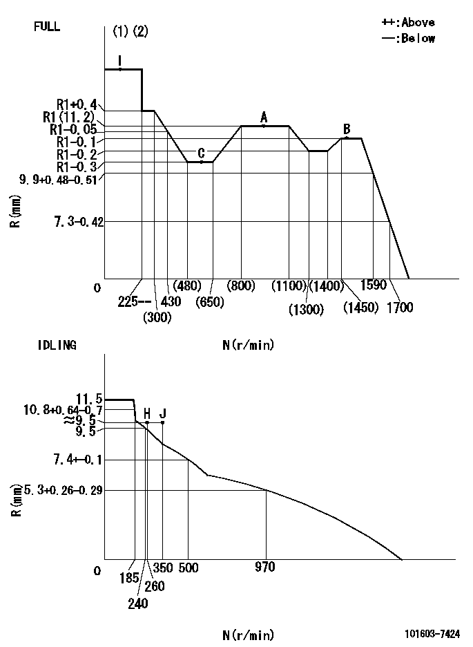
N:Pump speed
R:Rack position (mm)
(1)Torque cam stamping: T1
(2)Tolerance for racks not indicated: +-0.05mm.
----------
T1=F10
----------
----------
T1=F10
----------
Speed control lever angle

F:Full speed
I:Idle
(1)Use the pin at R = aa
(2)Stopper bolt set position 'H'
----------
aa=35mm
----------
a=11deg+-5deg b=(36.5deg)+-3deg
----------
aa=35mm
----------
a=11deg+-5deg b=(36.5deg)+-3deg
Stop lever angle

N:Pump normal
S:Stop the pump.
(1)Use the pin at R = aa
----------
aa=60mm
----------
a=16deg+-5deg b=29deg+-5deg
----------
aa=60mm
----------
a=16deg+-5deg b=29deg+-5deg
0000001501 AIR CYLINDER

1. (1) Set the speed lever to idle.
(2)Screw in air cylinder (A)
(3)Set the clearance from the speed lever (B) at approximately L.
----------
L=1mm
----------
----------
L=1mm
----------
0000001601 I/P WITH LOAD PLUNGER ADJ
Plunger assembly number: PL (stamping: ST)
1. Adjustment procedures
(1)Insert the pre-stroke adjusting shims L1 for each cylinder.
(2)Adjust injection quantity.(max. var. bet. cyl. idling a1, full a2)
(3)At basic point A, adjust so that the pre-stroke is L2.
(4)Reconfirm the injection quantity.
----------
PL=131153-4520 ST=A724 L1=1mm L2=4.2+-0.05mm a1=+-14% a2=+-2.5%
----------
----------
PL=131153-4520 ST=A724 L1=1mm L2=4.2+-0.05mm a1=+-14% a2=+-2.5%
----------
Timing setting
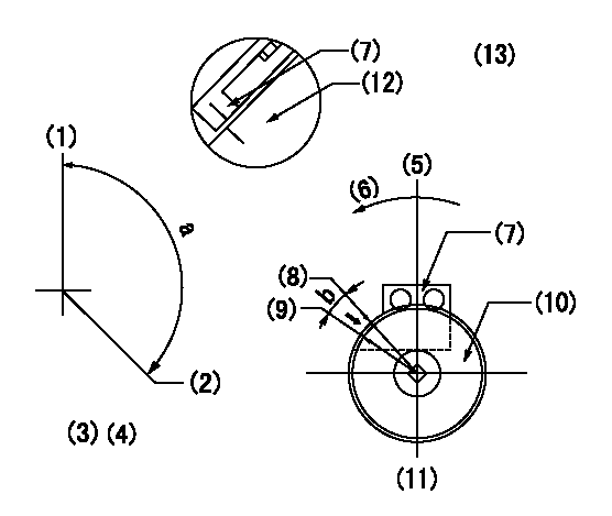
(1)Pump vertical direction
(2)Position of timer's threaded hole at No 1 cylinder's beginning of injection
(3)B.T.D.C.: aa
(4)-
(5)Pump vertical direction
(6)Direction of rotation
(7)Pointer
(8)Pointer stamping
(9)Timing device stamping
(10)Timing device
(11)Move b deg and stamp both at the same time as shown above.
(12)Outside circumference of timing device
(13)Secondary timing stamping position for the No. 1 cylinder's beginning of injection
----------
aa=11deg
----------
a=(150deg) b=1deg
----------
aa=11deg
----------
a=(150deg) b=1deg
Information:
1. Disconnect the fuel outlet line (1) and fuel inlet line (3) from the priming pump.2. Disconnect the fuel line (2) from pump.3. Remove the bolts (4) from pump.4. Remove the fuel transfer pump.5. Remove the fuel lines (1) and (3) from pump.Install Fuel Transfer Pump
1. Install the two fuel lines in transfer pump.2. Put the fuel transfer pump in position in the accessory drive housing, and install the two bolts.3. Connect the two fuel lines to priming pump.4. Connect the fuel line to transfer pump.Disassemble Fuel Transfer Pump
start by: a) remove fuel transfer pump 1. Remove the nut (2), gear (3), and key.2. Remove the cage (1). Remove the O-ring seals from the cage.3. Use tool setup (A) to remove the bearing and seals from cage (1).4. Remove the cover (4).
Be careful during disassembly and assembly of pump to prevent damage to the contacting surfaces of the cover (4) and the pump body.
5. Remove the bolt (5), spring, and ball for the check valve for the priming pump. 6. Remove the gear (7), and gear and shaft assembly (6) from pump body. 7. Use tool setup (A) to remove the bearing from the pump body.Assemble Fuel Transfer Pump
1. Clean all parts thoroughly before assembling the pump. 2. Use tool setup (A) to install the bearing in the pump body.3. Put the gear, and gear and shaft assembly in position in pump body.4. Put a thin amount of 8S6747 Liquid Gasket Material on the face of body assembly that is against the cover.
Do not let the liquid gasket material get into the pump.
5. Put the cover into position on pump body and install the bolts. The gear and shaft assembly must turn freely after the bolts in cover have been tightened.6. Install the check valve ball, spring, and bolt for the priming pump in the cover. 7. Use tool setup (B) to install the seals in cage. Install the two seals with the lips of seals toward each other.8. Use tool setup (A) to install the bearing in cage assembly. Install the O-ring seals on cage. 9. Put clean oil on O-ring seals and lips of seals. 10. Put the cage assembly in position, and install the woodruff key, gear, and nut. Tighten nut to 22 5 lb.ft. (3.0 0.7 mkg).end by: a) install fuel transfer pump