Information injection-pump assembly
ZEXEL
101603-7422
1016037422
ISUZU
8943965630
8943965630

Rating:
Cross reference number
ZEXEL
101603-7422
1016037422
ISUZU
8943965630
8943965630
Zexel num
Bosch num
Firm num
Name
Calibration Data:
Adjustment conditions
Test oil
1404 Test oil ISO4113 or {SAEJ967d}
1404 Test oil ISO4113 or {SAEJ967d}
Test oil temperature
degC
40
40
45
Nozzle and nozzle holder
105780-8210
Nozzle
105780-0070
Bosch type code
DN12SD12T-1
Nozzle holder
105780-2080
Bosch type code
EF8511/9
Opening pressure
MPa
17.2
Opening pressure
kgf/cm2
175
Injection pipe
Outer diameter - inner diameter - length (mm) mm 6-2-600
Outer diameter - inner diameter - length (mm) mm 6-2-600
Overflow valve
131424-4920
Overflow valve opening pressure
kPa
127
107
147
Overflow valve opening pressure
kgf/cm2
1.3
1.1
1.5
Tester oil delivery pressure
kPa
157
157
157
Tester oil delivery pressure
kgf/cm2
1.6
1.6
1.6
Direction of rotation (viewed from drive side)
Left L
Left L
Injection timing adjustment
Direction of rotation (viewed from drive side)
Left L
Left L
Injection order
1-5-3-6-
2-4
Pre-stroke
mm
4.2
4.15
4.25
Rack position
After adjusting injection quantity. R=A
After adjusting injection quantity. R=A
Beginning of injection position
Governor side NO.1
Governor side NO.1
Difference between angles 1
Cal 1-5 deg. 60 59.5 60.5
Cal 1-5 deg. 60 59.5 60.5
Difference between angles 2
Cal 1-3 deg. 120 119.5 120.5
Cal 1-3 deg. 120 119.5 120.5
Difference between angles 3
Cal 1-6 deg. 180 179.5 180.5
Cal 1-6 deg. 180 179.5 180.5
Difference between angles 4
Cyl.1-2 deg. 240 239.5 240.5
Cyl.1-2 deg. 240 239.5 240.5
Difference between angles 5
Cal 1-4 deg. 300 299.5 300.5
Cal 1-4 deg. 300 299.5 300.5
Injection quantity adjustment
Adjusting point
-
Rack position
11.2
Pump speed
r/min
900
900
900
Average injection quantity
mm3/st.
73.5
71.9
75.1
Max. variation between cylinders
%
0
-2.5
2.5
Basic
*
Fixing the rack
*
Standard for adjustment of the maximum variation between cylinders
*
Injection quantity adjustment_02
Adjusting point
H
Rack position
9.5+-0.5
Pump speed
r/min
260
260
260
Average injection quantity
mm3/st.
8.3
7
9.6
Max. variation between cylinders
%
0
-14
14
Fixing the rack
*
Standard for adjustment of the maximum variation between cylinders
*
Injection quantity adjustment_03
Adjusting point
A
Rack position
R1(11.2)
Pump speed
r/min
900
900
900
Average injection quantity
mm3/st.
73.5
72.5
74.5
Basic
*
Fixing the lever
*
Injection quantity adjustment_04
Adjusting point
B
Rack position
R1-0.1
Pump speed
r/min
1500
1500
1500
Average injection quantity
mm3/st.
84.6
80.6
88.6
Fixing the lever
*
Injection quantity adjustment_05
Adjusting point
C
Rack position
R1-0.3
Pump speed
r/min
600
600
600
Average injection quantity
mm3/st.
55.3
52.1
58.5
Fixing the lever
*
Injection quantity adjustment_06
Adjusting point
I
Rack position
-
Pump speed
r/min
150
150
150
Average injection quantity
mm3/st.
103
103
135
Fixing the lever
*
Timer adjustment
Pump speed
r/min
1210--
Advance angle
deg.
0
0
0
Load
3/4
Remarks
Start
Start
Timer adjustment_02
Pump speed
r/min
1160
Advance angle
deg.
0.3
Load
3/4
Timer adjustment_03
Pump speed
r/min
1500
Advance angle
deg.
5.5
5
6
Load
4/4
Remarks
Finish
Finish
Test data Ex:
Governor adjustment
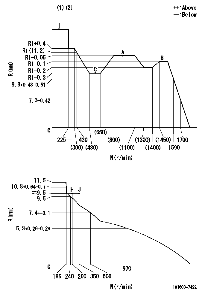
N:Pump speed
R:Rack position (mm)
(1)Torque cam stamping: T1
(2)Tolerance for racks not indicated: +-0.05mm.
----------
T1=F10
----------
----------
T1=F10
----------
Speed control lever angle

F:Full speed
I:Idle
(1)Use the pin at R = aa
(2)Stopper bolt set position 'H'
----------
aa=35mm
----------
a=11deg+-5deg b=(36.5deg)+-3deg
----------
aa=35mm
----------
a=11deg+-5deg b=(36.5deg)+-3deg
Stop lever angle

N:Pump normal
S:Stop the pump.
(1)Use the pin at R = aa
----------
aa=45mm
----------
a=12.5deg+-5deg b=40deg+-5deg
----------
aa=45mm
----------
a=12.5deg+-5deg b=40deg+-5deg
0000001501 AIR CYLINDER

1. (1) Set the speed lever to idle.
(2)Screw in air cylinder (A)
(3)Set the clearance from the speed lever (B) at approximately L.
----------
L=1mm
----------
----------
L=1mm
----------
0000001601 I/P WITH LOAD PLUNGER ADJ
Plunger assembly number: PL (stamping: ST)
1. Adjustment procedures
(1)Insert the pre-stroke adjusting shims L1 for each cylinder.
(2)Adjust injection quantity.(max. var. bet. cyl. idling a1, full a2)
(3)At basic point A, adjust so that the pre-stroke is L2.
(4)Reconfirm the injection quantity.
----------
PL=131153-4520 ST=A724 L1=1mm L2=4.2+-0.05mm a1=+-14% a2=+-2.5%
----------
----------
PL=131153-4520 ST=A724 L1=1mm L2=4.2+-0.05mm a1=+-14% a2=+-2.5%
----------
Timing setting

(1)Pump vertical direction
(2)Position of timer's threaded hole at No 1 cylinder's beginning of injection
(3)B.T.D.C.: aa
(4)-
----------
aa=11deg
----------
a=(150deg)
----------
aa=11deg
----------
a=(150deg)
Information:
CHECKING FLYWHEEL FACE RUNOUT4. The difference between the lowest and highest readings taken at all four points should not exceed .006 in. (0.15 mm), which is the maximum permissible flywheel face runout.Checking Flywheel Bore Runout
CHECKING FLYWHEEL BORE RUNOUT
1. 7H1945 Holding Rod. 2. 7H1645 Holding Rod. 3. 7H1942 Indicator. 4. 7H1940 Universal Attachment.Make tool setup from parts of the 8S2328 Dial Test Indicator Group.1. Mount the dial indicator and adjust it so the universal attachment contacts the flywheel bore as shown.2. Adjust the dial indicator to read .000 in. (0.0 mm) then take readings every 90° around the flywheel.3. The difference between the lowest and highest readings taken at all four points should not exceed .006 in. (0.15 mm), which is the maximum permissible flywheel bore runout. Flywheel clutch pilot bearing bore runout should not exceed .005 in. (0.13 mm).
CHECKING FLYWHEEL CLUTCH PILOT BEARING BOREElectrical System
Most of the testing of the electrical system can be done on the engine. The wiring insulation must be in good condition, the wire and cable connections clean and tight and the battery fully charged. If on the engine test shows a defect in a component, remove the component for more testing. The wire size, color and recommendations of length are given in the WIRING DIAGRAMS in SYSTEMS OPERATION.Battery
9S1990 Battery Charger Tester.The battery circuit is an electrical load on the charging unit. The load is variable because of the condition of the charge in the battery. Damage to the charging unit will result, if the connections, (either positive or negative) between the battery and charging unit are broken while the charging unit is charging. This is because the battery load is lost and there is an increase in charging voltage.High voltage will damage, not only the charging unit but also the regulator and other electrical components.
9S1990 BATTERY CHARGER TESTER
Never disconnect any charging unit circuit or battery circuit cable from battery when the charging unit is charging.
Load test a battery that does not hold a charge when in use. To do this, put a resistance, across the battery main connections (terminals). For a 6 volt battery, put a resistance of two times the ampere/hour rating of the battery. For a 12 volt battery, put a resistance of three times the ampere/hour rating. Let the resistance remove the charge (discharge the battery) for 15 seconds. Immediately test the battery voltage. A 6 volt battery in good condition will test 4.5 volts; a 12 volt battery in good condition will test 9 volts.The Special Instruction (GEG00058) with the 9S1990 Charger Tester gives the battery testing procedure.Charging System
Battery
The condition of charge in the battery at each regular inspection will show if the charging system is operating correctly. An adjustment is necessary when the battery is always in a low condition of charge or a large amount of water is needed (one ounce per cell per week or every 50 service hours).Test the charging units and voltage regulators on the engine, when possible, using wiring and components that are