Information injection-pump assembly
ZEXEL
101603-7421
1016037421
ISUZU
8943960312
8943960312

Rating:
Cross reference number
ZEXEL
101603-7421
1016037421
ISUZU
8943960312
8943960312
Zexel num
Bosch num
Firm num
Name
Calibration Data:
Adjustment conditions
Test oil
1404 Test oil ISO4113 or {SAEJ967d}
1404 Test oil ISO4113 or {SAEJ967d}
Test oil temperature
degC
40
40
45
Nozzle and nozzle holder
105780-8210
Nozzle
105780-0070
Bosch type code
DN12SD12T-1
Nozzle holder
105780-2080
Bosch type code
EF8511/9
Opening pressure
MPa
17.2
Opening pressure
kgf/cm2
175
Injection pipe
Outer diameter - inner diameter - length (mm) mm 6-2-600
Outer diameter - inner diameter - length (mm) mm 6-2-600
Overflow valve
131424-4920
Overflow valve opening pressure
kPa
127
107
147
Overflow valve opening pressure
kgf/cm2
1.3
1.1
1.5
Tester oil delivery pressure
kPa
157
157
157
Tester oil delivery pressure
kgf/cm2
1.6
1.6
1.6
Direction of rotation (viewed from drive side)
Left L
Left L
Injection timing adjustment
Direction of rotation (viewed from drive side)
Left L
Left L
Injection order
1-5-3-6-
2-4
Pre-stroke
mm
4.2
4.15
4.25
Rack position
After adjusting injection quantity. R=A
After adjusting injection quantity. R=A
Beginning of injection position
Governor side NO.1
Governor side NO.1
Difference between angles 1
Cal 1-5 deg. 60 59.5 60.5
Cal 1-5 deg. 60 59.5 60.5
Difference between angles 2
Cal 1-3 deg. 120 119.5 120.5
Cal 1-3 deg. 120 119.5 120.5
Difference between angles 3
Cal 1-6 deg. 180 179.5 180.5
Cal 1-6 deg. 180 179.5 180.5
Difference between angles 4
Cyl.1-2 deg. 240 239.5 240.5
Cyl.1-2 deg. 240 239.5 240.5
Difference between angles 5
Cal 1-4 deg. 300 299.5 300.5
Cal 1-4 deg. 300 299.5 300.5
Injection quantity adjustment
Adjusting point
-
Rack position
11.2
Pump speed
r/min
900
900
900
Average injection quantity
mm3/st.
73.5
71.9
75.1
Max. variation between cylinders
%
0
-2.5
2.5
Basic
*
Fixing the rack
*
Standard for adjustment of the maximum variation between cylinders
*
Injection quantity adjustment_02
Adjusting point
H
Rack position
9.5+-0.5
Pump speed
r/min
260
260
260
Average injection quantity
mm3/st.
8.3
7
9.6
Max. variation between cylinders
%
0
-14
14
Fixing the rack
*
Standard for adjustment of the maximum variation between cylinders
*
Injection quantity adjustment_03
Adjusting point
A
Rack position
R1(11.2)
Pump speed
r/min
900
900
900
Average injection quantity
mm3/st.
73.5
72.5
74.5
Basic
*
Fixing the lever
*
Injection quantity adjustment_04
Adjusting point
B
Rack position
R1-0.1
Pump speed
r/min
1500
1500
1500
Average injection quantity
mm3/st.
84.6
80.6
88.6
Fixing the lever
*
Injection quantity adjustment_05
Adjusting point
C
Rack position
R1-0.3
Pump speed
r/min
600
600
600
Average injection quantity
mm3/st.
55.3
52.1
58.5
Fixing the lever
*
Injection quantity adjustment_06
Adjusting point
I
Rack position
-
Pump speed
r/min
150
150
150
Average injection quantity
mm3/st.
103
103
135
Fixing the lever
*
Timer adjustment
Pump speed
r/min
1210--
Advance angle
deg.
0
0
0
Load
3/4
Remarks
Start
Start
Timer adjustment_02
Pump speed
r/min
1160
Advance angle
deg.
0.3
Load
3/4
Timer adjustment_03
Pump speed
r/min
1500
Advance angle
deg.
5.5
5
6
Load
4/4
Remarks
Finish
Finish
Test data Ex:
Governor adjustment
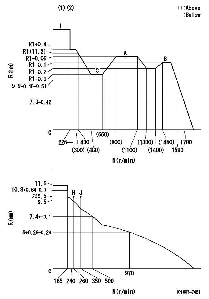
N:Pump speed
R:Rack position (mm)
(1)Torque cam stamping: T1
(2)Tolerance for racks not indicated: +-0.05mm.
----------
T1=E76
----------
----------
T1=E76
----------
Speed control lever angle

F:Full speed
I:Idle
(1)Use the pin at R = aa
(2)Stopper bolt set position 'H'
----------
aa=35mm
----------
a=11deg+-5deg b=(36.5deg)+-3deg
----------
aa=35mm
----------
a=11deg+-5deg b=(36.5deg)+-3deg
Stop lever angle

N:Pump normal
S:Stop the pump.
----------
----------
a=12.5deg+-5deg b=40deg+-5deg
----------
----------
a=12.5deg+-5deg b=40deg+-5deg
0000001501 AIR CYLINDER

1. (1) Set the speed lever to idle.
(2)Screw in air cylinder (A)
(3)Set the clearance from the speed lever (B) at approximately L.
----------
L=1mm
----------
----------
L=1mm
----------
0000001601 I/P WITH LOAD PLUNGER ADJ
Plunger assembly number: PL (stamping: ST)
1. Adjustment procedures
(1)Insert the pre-stroke adjusting shims L1 for each cylinder.
(2)Adjust injection quantity.(max. var. bet. cyl. idling a1, full a2)
(3)At basic point A, adjust so that the pre-stroke is L2.
(4)Reconfirm the injection quantity.
----------
PL=131153-4520 ST=A724 L1=1mm L2=4.2+-0.05mm a1=+-14% a2=+-2.5%
----------
----------
PL=131153-4520 ST=A724 L1=1mm L2=4.2+-0.05mm a1=+-14% a2=+-2.5%
----------
Timing setting

(1)Pump vertical direction
(2)Position of timer's threaded hole at No 1 cylinder's beginning of injection
(3)B.T.D.C.: aa
(4)-
----------
aa=10deg
----------
a=(150deg)
----------
aa=10deg
----------
a=(150deg)
Information:
COOLING SYSTEM FLOW DIAGRAM
1. Cylinder head. 2. Aftercooler. 3. Water temperature regulator housing. 4. Coolant outlet from radiator. 5. Air compressor. 6. Bypass water line. 7. Coolant outlet to aftercooler. 8. Water manifold. 9. Coolant outlet to water manifold. 10. Cylinder block. 11. Oil cooler. 12. Coolant inlet to water pump. 13. Water pump. 14. Shunt line. 15. Radiator. 16. Vent line. 17. Upper chamber. 18. Bleed tube. 19. Lower chamber.This engine has a pressurized cooling system. Coolant is circulated by a belt driven, centrifugal type water pump. A water temperature regulator, located at the left front of the cylinder head, restricts coolant flow through the radiator until the coolant reaches operating temperature.The water pump has two outlets. One outlet directs coolant through a passage in the water temperature regulator housing to the aftercooler, to lower the temperature of inlet air in the inlet manifold. The other water outlet directs coolant through a water manifold in the side of the cylinder block, to cool engine lubricating oil. Coolant flows from the water manifold around the cylinder liners, into the cylinder head and around the precombustion chambers. Both streams of water join at the water temperature regulator.The water cooled air compressor receives coolant through a tube that is connected to the water manifold in the side of the cylinder block. Coolant returns through a tube from the air compressor head to the diesel engine cylinder head.Until the coolant reaches the temperature required to open the temperature regulator, coolant bypasses the radiator and flows directly back to the water pump.When the coolant reaches the temperature required to open the temperature regulator, coolant is then directed to the radiator lower chamber.The upper chamber of the radiator receives any air in the lower chamber by way of the bleed tube. Any air in the engine is vented to the radiator upper chamber thru the vent line. The shunt line from the upper chamber to the inlet of the water pump provides for rapid filling of the system.A pressure relief cap assembly is used to control the pressure in the cooling system, and prevents loss of coolant through the radiator overflow tube.Pressurizing the cooling system serves two purposes. First, it permits safe operation at coolant temperatures higher than the normal boiling point, providing a margin of cooling for intermittent peak loads. Secondly, it prevents cavitation in the water pump, and reduces the possibility of air or steam pockets forming in the coolant passages. Proper operation of the pressure relief cap assembly is essential. A pressure relief cap allows pressure (and some water, if the cooling system is too full) to escape when the pressure in the cooling system exceeds the capacity of the pressure cap. Loss of pressure will cause steam to form when coolant temperature is above the normal boiling point.Cooling System Components
Water Pump
The centrifugal-type water pump has two seals, one prevents leakage of water and the other prevents leakage of lubricant.An opening in the bottom of the pump housing allows any