Information injection-pump assembly
ZEXEL
101603-7401
1016037401
ISUZU
1156026591
1156026591

Rating:
Cross reference number
ZEXEL
101603-7401
1016037401
ISUZU
1156026591
1156026591
Zexel num
Bosch num
Firm num
Name
Calibration Data:
Adjustment conditions
Test oil
1404 Test oil ISO4113 or {SAEJ967d}
1404 Test oil ISO4113 or {SAEJ967d}
Test oil temperature
degC
40
40
45
Nozzle and nozzle holder
105780-8210
Nozzle
105780-0070
Bosch type code
DN12SD12T-1
Nozzle holder
105780-2080
Bosch type code
EF8511/9
Opening pressure
MPa
17.2
Opening pressure
kgf/cm2
175
Injection pipe
Outer diameter - inner diameter - length (mm) mm 6-2-600
Outer diameter - inner diameter - length (mm) mm 6-2-600
Overflow valve
131424-4920
Overflow valve opening pressure
kPa
127
107
147
Overflow valve opening pressure
kgf/cm2
1.3
1.1
1.5
Tester oil delivery pressure
kPa
157
157
157
Tester oil delivery pressure
kgf/cm2
1.6
1.6
1.6
Direction of rotation (viewed from drive side)
Left L
Left L
Injection timing adjustment
Direction of rotation (viewed from drive side)
Left L
Left L
Injection order
1-5-3-6-
2-4
Pre-stroke
mm
3.7
3.65
3.75
Rack position
After adjusting injection quantity. R=A
After adjusting injection quantity. R=A
Beginning of injection position
Governor side NO.1
Governor side NO.1
Difference between angles 1
Cal 1-5 deg. 60 59.5 60.5
Cal 1-5 deg. 60 59.5 60.5
Difference between angles 2
Cal 1-3 deg. 120 119.5 120.5
Cal 1-3 deg. 120 119.5 120.5
Difference between angles 3
Cal 1-6 deg. 180 179.5 180.5
Cal 1-6 deg. 180 179.5 180.5
Difference between angles 4
Cyl.1-2 deg. 240 239.5 240.5
Cyl.1-2 deg. 240 239.5 240.5
Difference between angles 5
Cal 1-4 deg. 300 299.5 300.5
Cal 1-4 deg. 300 299.5 300.5
Injection quantity adjustment
Adjusting point
-
Rack position
12.3
Pump speed
r/min
700
700
700
Average injection quantity
mm3/st.
79
77.4
80.6
Max. variation between cylinders
%
0
-2.5
2.5
Basic
*
Fixing the rack
*
Standard for adjustment of the maximum variation between cylinders
*
Injection quantity adjustment_02
Adjusting point
H
Rack position
9.5+-0.5
Pump speed
r/min
260
260
260
Average injection quantity
mm3/st.
9.1
7.1
11.1
Max. variation between cylinders
%
0
-14
14
Fixing the rack
*
Standard for adjustment of the maximum variation between cylinders
*
Injection quantity adjustment_03
Adjusting point
A
Rack position
R1(12.3)
Pump speed
r/min
700
700
700
Average injection quantity
mm3/st.
79
78
80
Basic
*
Fixing the lever
*
Injection quantity adjustment_04
Adjusting point
B
Rack position
R1+0.1
Pump speed
r/min
1350
1350
1350
Average injection quantity
mm3/st.
92.2
89
95.4
Fixing the lever
*
Injection quantity adjustment_05
Adjusting point
I
Rack position
-
Pump speed
r/min
150
150
150
Average injection quantity
mm3/st.
121
121
153
Fixing the lever
*
Timer adjustment
Pump speed
r/min
900--
Advance angle
deg.
0
0
0
Remarks
Start
Start
Timer adjustment_02
Pump speed
r/min
850
Advance angle
deg.
0.5
Timer adjustment_03
Pump speed
r/min
(900)
Advance angle
deg.
1
0.5
1.5
Remarks
Measure the actual speed.
Measure the actual speed.
Timer adjustment_04
Pump speed
r/min
1125
Advance angle
deg.
1
0.5
1.5
Timer adjustment_05
Pump speed
r/min
1275
Advance angle
deg.
5
4.5
5.5
Remarks
Finish
Finish
Test data Ex:
Governor adjustment
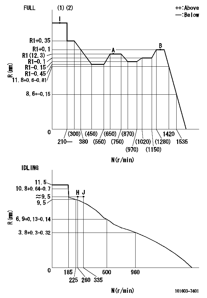
N:Pump speed
R:Rack position (mm)
(1)Torque cam stamping: T1
(2)Tolerance for racks not indicated: +-0.05mm.
----------
T1=E94
----------
----------
T1=E94
----------
Speed control lever angle

F:Full speed
I:Idle
(1)Stopper bolt set position 'H'
----------
----------
a=20deg+-5deg b=(39deg)+-3deg
----------
----------
a=20deg+-5deg b=(39deg)+-3deg
Stop lever angle
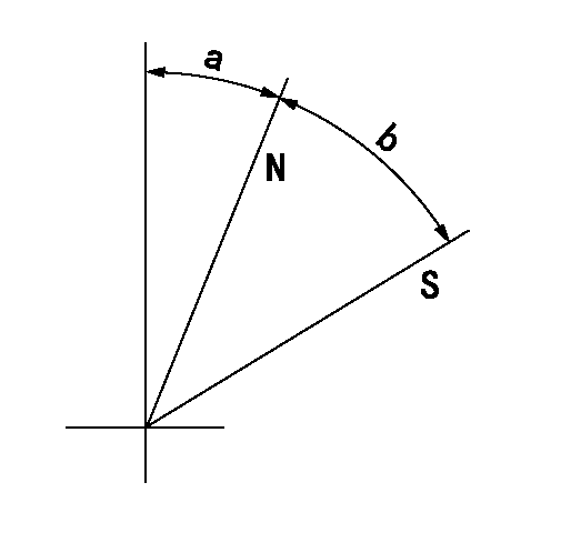
N:Pump normal
S:Stop the pump.
----------
----------
a=25deg+-5deg b=40deg+-5deg
----------
----------
a=25deg+-5deg b=40deg+-5deg
0000001501 I/P WITH LOAD PLUNGER ADJ
Plunger assembly number: PL (stamping: ST)
1. Adjustment procedures
(1)Insert the pre-stroke adjusting shims L1 for each cylinder.
(2)Adjust injection quantity.(max. var. bet. cyl. idling a1, full a2)
(3)At basic point A, adjust so that the pre-stroke is L2.
(4)Reconfirm the injection quantity.
----------
PL=131153-4620 ST=A725 L1=1mm L2=3.7+-0.05mm a1=+-14% a2=+-2.5%
----------
----------
PL=131153-4620 ST=A725 L1=1mm L2=3.7+-0.05mm a1=+-14% a2=+-2.5%
----------
Timing setting

(1)Pump vertical direction
(2)Position of timer's threaded hole at No 1 cylinder's beginning of injection
(3)B.T.D.C.: aa
(4)-
----------
aa=8.5deg
----------
a=(40deg)
----------
aa=8.5deg
----------
a=(40deg)
Information:
ACTION REQUIRED
Take the following actions after a failure occurs on one or more injectors in any of the engines in the Affected Product. A failure is considered extreme fuel dilution, in the range of 20 liters per minute.
- If one or more injectors fail it may be necessary to replace additional injectors at the time of repair.
- Verify the injector serial number of the failed injector. Verify the injector serial number of the remaining injectors in the engine. Refer to Image1 for an example of part number (A) and injector serial number identification (B). If the injector serial number falls within the range of 1134640-1234085, the injector should be replaced. The 154-6389 Buttons on the engine should also be replaced. The 154-6389 Button and 9F-7707 Retaining Clip on the injector rocker arms should also be replaced.
Only injectors falling within the range of 1134640-1234085 should be replaced and claimed under this program.
Refer to the Disassembly and Assembly manual for the removal/installation procedure of the unit injector and button.
Excessive fuel dilution of the engine oil requires changing the engine oil and filters. Refer to the appropriate Service Manual as necessary.
Image1
SERVICE CLAIM ALLOWANCES
Product smu/age whichever comes first Caterpillar Dealer Suggested Customer Suggested
Parts % Labor Hrs% Parts % Labor Hrs% Parts % Labor Hrs%
*******Group 1*******
0-3000 hrs,
0-36 mo 100.0% 100.0% 0.0% 0.0% 0.0% 0.0%
This is a 2.6-hour job for Group 1
An additional 0.6 hours labor will be allowed per injector replaced due to inspection results.
Product smu/age whichever comes first Caterpillar Dealer Suggested Customer Suggested
Parts % Labor Hrs% Parts % Labor Hrs% Parts % Labor Hrs%
*******Group 2*******
0-3000 hrs,
0-36 mo 100.0% 100.0% 0.0% 0.0% 0.0% 0.0%
This is a 2.6-hour job for Group 2
An additional 0.6 hours labor will be allowed per injector replaced due to inspection results.
PARTS DISPOSITION
Handle the parts in accordance with your Warranty Bulletin on warranty parts handling.