Information injection-pump assembly
BOSCH
F 01G 09U 047
f01g09u047
ZEXEL
101603-7288
1016037288
ISUZU
8943965705
8943965705
Rating:
Service parts 101603-7288 INJECTION-PUMP ASSEMBLY:
1.
_
7.
COUPLING PLATE
8.
_
9.
_
11.
Nozzle and Holder
8-94397-054-0
12.
Open Pre:MPa(Kqf/cm2)
18.1{185}
15.
NOZZLE SET
Include in #1:
101603-7288
as INJECTION-PUMP ASSEMBLY
Include in #2:
104134-3010
as _
Cross reference number
BOSCH
F 01G 09U 047
f01g09u047
ZEXEL
101603-7288
1016037288
ISUZU
8943965705
8943965705
Zexel num
Bosch num
Firm num
Name
Calibration Data:
Adjustment conditions
Test oil
1404 Test oil ISO4113 or {SAEJ967d}
1404 Test oil ISO4113 or {SAEJ967d}
Test oil temperature
degC
40
40
45
Nozzle and nozzle holder
105780-8140
Bosch type code
EF8511/9A
Nozzle
105780-0000
Bosch type code
DN12SD12T
Nozzle holder
105780-2080
Bosch type code
EF8511/9
Opening pressure
MPa
17.2
Opening pressure
kgf/cm2
175
Injection pipe
Outer diameter - inner diameter - length (mm) mm 6-2-600
Outer diameter - inner diameter - length (mm) mm 6-2-600
Overflow valve opening pressure
kPa
157
123
191
Overflow valve opening pressure
kgf/cm2
1.6
1.25
1.95
Tester oil delivery pressure
kPa
157
157
157
Tester oil delivery pressure
kgf/cm2
1.6
1.6
1.6
Direction of rotation (viewed from drive side)
Left L
Left L
Injection timing adjustment
Direction of rotation (viewed from drive side)
Left L
Left L
Injection order
1-5-3-6-
2-4
Pre-stroke
mm
3.7
3.65
3.75
Rack position
After adjusting injection quantity. R=A
After adjusting injection quantity. R=A
Beginning of injection position
Governor side NO.1
Governor side NO.1
Difference between angles 1
Cal 1-5 deg. 60 59.5 60.5
Cal 1-5 deg. 60 59.5 60.5
Difference between angles 2
Cal 1-3 deg. 120 119.5 120.5
Cal 1-3 deg. 120 119.5 120.5
Difference between angles 3
Cal 1-6 deg. 180 179.5 180.5
Cal 1-6 deg. 180 179.5 180.5
Difference between angles 4
Cyl.1-2 deg. 240 239.5 240.5
Cyl.1-2 deg. 240 239.5 240.5
Difference between angles 5
Cal 1-4 deg. 300 299.5 300.5
Cal 1-4 deg. 300 299.5 300.5
Injection quantity adjustment
Adjusting point
-
Rack position
12.2
Pump speed
r/min
900
900
900
Average injection quantity
mm3/st.
63
61.4
64.6
Max. variation between cylinders
%
0
-2.5
2.5
Basic
*
Fixing the rack
*
Standard for adjustment of the maximum variation between cylinders
*
Injection quantity adjustment_02
Adjusting point
H
Rack position
9.5+-0.5
Pump speed
r/min
260
260
260
Average injection quantity
mm3/st.
8
6.7
9.3
Max. variation between cylinders
%
0
-14
14
Fixing the rack
*
Standard for adjustment of the maximum variation between cylinders
*
Injection quantity adjustment_03
Adjusting point
A
Rack position
R1(12.2)
Pump speed
r/min
900
900
900
Average injection quantity
mm3/st.
63
62
64
Basic
*
Fixing the lever
*
Injection quantity adjustment_04
Adjusting point
B
Rack position
R1+0.1
Pump speed
r/min
1400
1400
1400
Average injection quantity
mm3/st.
71.1
67.9
74.3
Fixing the lever
*
Injection quantity adjustment_05
Adjusting point
I
Rack position
-
Pump speed
r/min
150
150
150
Average injection quantity
mm3/st.
102
102
134
Fixing the lever
*
Timer adjustment
Pump speed
r/min
1150
Advance angle
deg.
0.5
Timer adjustment_02
Pump speed
r/min
1300
Advance angle
deg.
2
1.5
2.5
Timer adjustment_03
Pump speed
r/min
1500
Advance angle
deg.
5.5
5
6
Remarks
Finish
Finish
Test data Ex:
Governor adjustment
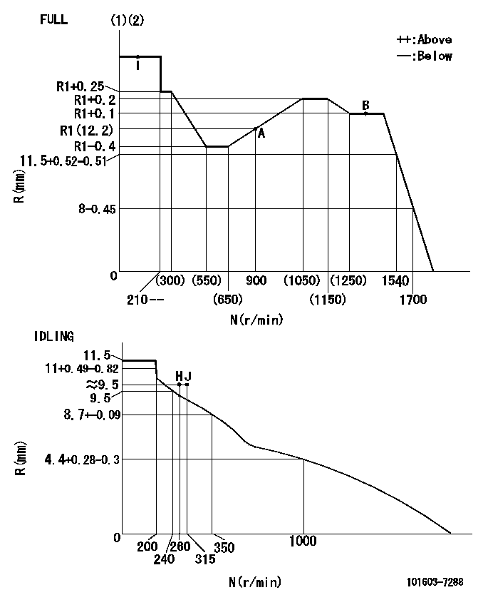
N:Pump speed
R:Rack position (mm)
(1)Torque cam stamping: T1
(2)Tolerance for racks not indicated: +-0.05mm.
----------
T1=G23
----------
----------
T1=G23
----------
Speed control lever angle
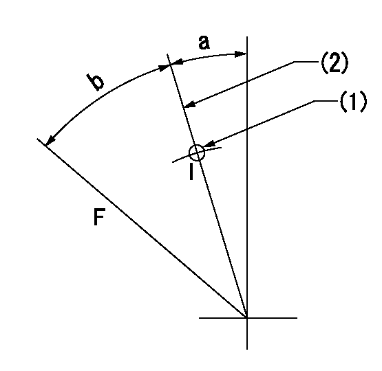
F:Full speed
I:Idle
(1)Use the pin at R = aa
(2)Stopper bolt set position 'H'
----------
aa=35mm
----------
a=11deg+-5deg b=(40deg)+-3deg
----------
aa=35mm
----------
a=11deg+-5deg b=(40deg)+-3deg
Stop lever angle
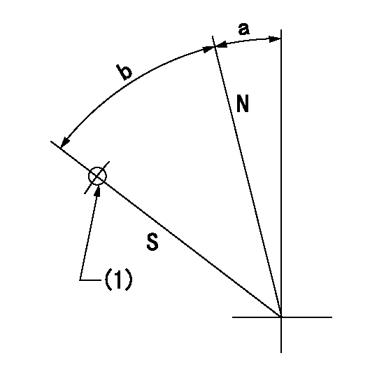
N:Pump normal
S:Stop the pump.
(1)Use the pin at R = aa
----------
aa=67mm
----------
a=16deg+-5deg b=29deg+-5deg
----------
aa=67mm
----------
a=16deg+-5deg b=29deg+-5deg
0000001501 I/P WITH LOAD PLUNGER ADJ
Plunger assembly number: PL (stamping: ST)
1. Adjustment procedures
(1)Insert the pre-stroke adjusting shims L1 for each cylinder.
(2)Adjust injection quantity.(max. var. bet. cyl. idling a1, full a2)
(3)At basic point A, adjust so that the pre-stroke is L2.
(4)Reconfirm the injection quantity.
----------
PL=131154-1320 ST=A255 L1=1mm L2=3.7+-0.05mm a1=+-14% a2=+-2.5%
----------
----------
PL=131154-1320 ST=A255 L1=1mm L2=3.7+-0.05mm a1=+-14% a2=+-2.5%
----------
Timing setting
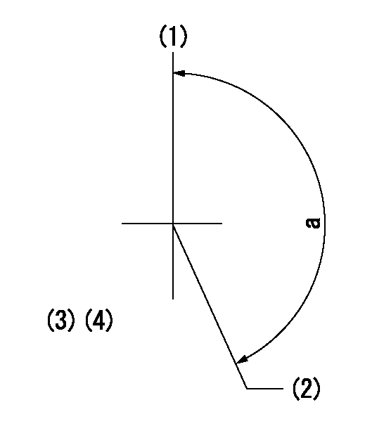
(1)Pump vertical direction
(2)Position of timer's threaded hole at No 1 cylinder's beginning of injection
(3)B.T.D.C.: aa
(4)-
----------
aa=10deg
----------
a=(160deg)
----------
aa=10deg
----------
a=(160deg)
Information:
TERMINATION DATE
31Jul2009
PROBLEM
The existing HEUI pump, Injector O-rings, and/or Fuel Pressure Regulator can fail on certain On-Highway Mass Transit Bus Engines.
AFFECTED PRODUCT
Model Identification Number
C9 MTB01000, 1005, 1007-1014, 1016-1078, 1087-1090, 1093-1095, 1097, 1099, 1101, 1103-1104, 1109-1110, 1117-1129, 1131-1134, 1136, 1140-1141, 1143-1144, 1147, 1149-1150, 1159-1162, 1172-1176, 1179-1181, 1183-1184, 1186, 1188, 1190-1196, 1198-1202, 1205-1208, 1217, 1221, 1227-1233, 1235, 1238, 1240-1241, 1244-1245, 1248-1252, 1255-1256, 1261-1265, 1267, 1269, 1272-1273, 1278, 1285-1289, 1293, 1298, 1301-1306, 1311-1322, 1324-1343, 1345-1353, 1355-1363, 1365-1366, 1368, 1371-1372, 1374, 1380-1381, 1384-1386, 1396, 1398-1400, 1402, 1404, 1406, 1409, 1411, 1415, 1418, 1420-1421, 1425-1426, 1428-1429, 1431-1432, 1434-1464, 1467-1468, 1470, 1473-1474, 1476-1477, 1480, 1482-1483, 1486-1489, 1491-1493, 1497-1498, 1521, 1555, 1558-1560, 1654-1656, 1687-1689, 1700-1706, 1837-1842, 1853-1858, 1869-1878, 1884-1886, 1893, 1896-1897, 1899, 1918, 1921, 1924-1926, 1928-1929, 1931-1943, 1992-1993, 1996-1997, 2001, 2006
PARTS NEEDED
Qty
Part Number Description
1 6V4589 SEAL-O-RING
1 1093207 SEAL-O-RING
2 1482903 SEAL-O-RING
1 1495240 RING-BACKUP
1 2930730 RING-BACKUP
1 2948620 REGULATOR AS.
1 3120678 PUMP GP -B
ACTION REQUIRED
Follow SENR9674 Disassembly and Assembly Guide for installation of updated HEUI Pump, Injector O-rings, and Fuel Pressure Regulator.
Reference SEBD6792 for correct orientation of Injector O-rings.
SERVICE CLAIM ALLOWANCES
Product smu/age whichever comes first Caterpillar Dealer Suggested Customer Suggested
Parts % Labor Hrs% Parts % Labor Hrs% Parts % Labor Hrs%
0-12000 hrs 100.0% 100.0% 0.0% 0.0% 0.0% 0.0%
This is a 7.5-hour job
*Dealer to perform most economical repair*
Description_________SMCS__________Hours
R&I Injectors_____1290-010-S______4.2hrs
Wash______________1290-074________0.3hrs
Test After________1290-030________0.5hrs
R&I HEUI PUMP_____1714-010________1.1hrs
Pump Test After___1714-030________0.5hrs
R&I Regulator_____1715-010________0.9hrs
*Exception may be considered and claimed depending on chassis type*
PARTS DISPOSITION
Handle the parts in accordance with your Warranty Bulletin on warranty parts handling.