Information injection-pump assembly
BOSCH
9 400 615 163
9400615163
ZEXEL
101603-7150
1016037150
Rating:
Include in #2:
104741-1970
as _
Cross reference number
BOSCH
9 400 615 163
9400615163
ZEXEL
101603-7150
1016037150
Zexel num
Bosch num
Firm num
Name
101603-7150
9 400 615 163
INJECTION-PUMP ASSEMBLY
6SA1-T * 14BF PE6AD PE
6SA1-T * 14BF PE6AD PE
101603-7150
9 400 615 163
1156025390 ISUZU
INJECTION-PUMP ASSEMBLY
6SA1-T * 14BF PE6AD PE
6SA1-T * 14BF PE6AD PE
Calibration Data:
Adjustment conditions
Test oil
1404 Test oil ISO4113 or {SAEJ967d}
1404 Test oil ISO4113 or {SAEJ967d}
Test oil temperature
degC
40
40
45
Nozzle and nozzle holder
105780-8140
Bosch type code
EF8511/9A
Nozzle
105780-0000
Bosch type code
DN12SD12T
Nozzle holder
105780-2080
Bosch type code
EF8511/9
Opening pressure
MPa
17.2
Opening pressure
kgf/cm2
175
Injection pipe
Outer diameter - inner diameter - length (mm) mm 6-2-600
Outer diameter - inner diameter - length (mm) mm 6-2-600
Overflow valve
131424-4920
Overflow valve opening pressure
kPa
127
107
147
Overflow valve opening pressure
kgf/cm2
1.3
1.1
1.5
Tester oil delivery pressure
kPa
157
157
157
Tester oil delivery pressure
kgf/cm2
1.6
1.6
1.6
Direction of rotation (viewed from drive side)
Left L
Left L
Injection timing adjustment
Direction of rotation (viewed from drive side)
Left L
Left L
Injection order
1-5-3-6-
2-4
Pre-stroke
mm
4.7
4.65
4.75
Beginning of injection position
Governor side NO.1
Governor side NO.1
Difference between angles 1
Cal 1-5 deg. 60 59.5 60.5
Cal 1-5 deg. 60 59.5 60.5
Difference between angles 2
Cal 1-3 deg. 120 119.5 120.5
Cal 1-3 deg. 120 119.5 120.5
Difference between angles 3
Cal 1-6 deg. 180 179.5 180.5
Cal 1-6 deg. 180 179.5 180.5
Difference between angles 4
Cyl.1-2 deg. 240 239.5 240.5
Cyl.1-2 deg. 240 239.5 240.5
Difference between angles 5
Cal 1-4 deg. 300 299.5 300.5
Cal 1-4 deg. 300 299.5 300.5
Injection quantity adjustment
Adjusting point
A
Rack position
8.9
Pump speed
r/min
900
900
900
Average injection quantity
mm3/st.
87.6
86.6
88.6
Max. variation between cylinders
%
0
-2.5
2.5
Basic
*
Fixing the lever
*
Injection quantity adjustment_02
Adjusting point
B
Rack position
6+-0.5
Pump speed
r/min
325
325
325
Average injection quantity
mm3/st.
9
7
11
Max. variation between cylinders
%
0
-14
14
Fixing the rack
*
Timer adjustment
Pump speed
r/min
850--
Advance angle
deg.
0
0
0
Remarks
Start
Start
Timer adjustment_02
Pump speed
r/min
800
Advance angle
deg.
0.5
Timer adjustment_03
Pump speed
r/min
1120
Advance angle
deg.
1
0.5
1.5
Remarks
Finish
Finish
Test data Ex:
Governor adjustment
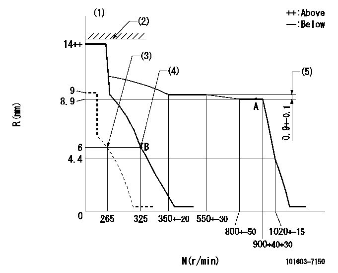
N:Pump speed
R:Rack position (mm)
(1)Target notch: K
(2)RACK LIMIT not operating.
(3)Set idle sub-spring
(4)Main spring setting
(5)Rack difference between N = N1 and N = N2
----------
K=7 N1=900r/min N2=500r/min
----------
----------
K=7 N1=900r/min N2=500r/min
----------
Speed control lever angle
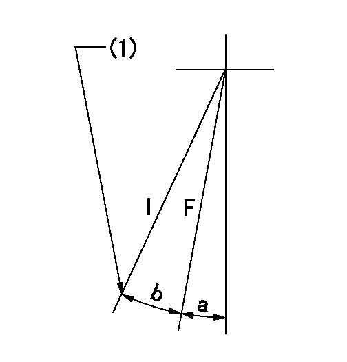
F:Full speed
I:Idle
(1)Stopper bolt setting
----------
----------
a=(1deg)+-5deg b=(19deg)+-5deg
----------
----------
a=(1deg)+-5deg b=(19deg)+-5deg
Stop lever angle

N:Pump normal
S:Stop the pump.
----------
----------
a=19deg+-5deg b=53deg+-5deg
----------
----------
a=19deg+-5deg b=53deg+-5deg
Timing setting

(1)Pump vertical direction
(2)Position of timer's threaded hole at No 1 cylinder's beginning of injection
(3)B.T.D.C.: aa
(4)-
----------
aa=18deg
----------
a=(40deg)
----------
aa=18deg
----------
a=(40deg)
Information:
Installation Procedure
Illustration 1 g06123834
Remove support (1) from the engine compartment.
Illustration 2 g06123840
Locate insulation (2) on the engine hood.
Illustration 3 g06123843
Raise the insulation approximately 30 mm (1.2 inch) to avoid interference with the new tank.
Illustration 4 g06123848
Loosen the worm-drive clamps and remove two hoses (3) from the DEF system. Save the cushion clamps and hardware for reuse.
Illustration 5 g06123850
(4) 428-8808 Hose Clamp
(5) 467-9633 Hose
(6) Cushion clamp (reuse)
Install hose (5) and two clamps (4). Slowly tighten the clamps to 6.6 0.2 N m (58 1.8 lb in). Install cushion clamp (6) (previously removed) onto the hose.
Illustration 6 g06123852
(4) 428-8808 Hose Clamp
(6) Cushion clamp (reuse)
(7) 469-6277 Hose
(8) 424-1209 Tank
Connect one end of hose (7) to the tube on the engine using clamp (4). Slowly tighten the clamp to 6.6 0.2 N m (58 1.8 lb in). Install cushion clamp (6) (previously removed) onto the hose.
Connect the other end of the hose to the upper port on tank (8). Install clamp (4). Slowly tighten the clamp to 6.6 0.2 N m (58 1.8 lb in).
Illustration 7 g06123862
(4) 428-8808 Hose Clamp
(9) 469-9636 Hose
(10) 6V-3250 O-Ring Seal
(11) 7X-1448 Elbow
Install elbow (11) and O-Ring seal (10) on the tank. Install hose (9) using two hose clamps (4). Slowly tighten the clamps to 6.6 0.2 N m (58 1.8 lb in) while ensuring hose (9) stays at a 30 degree angle from the top tank hose.
Illustration 8 g06123868
(12) 454-4235 Plate
(13) 326-4516 Cable Tie
Secure the two hoses together using plate (12) and two cable ties (13).
Illustration 9 g06123873
(8) 424-1209 Tank
(14) 471-9825 Support As
(15) 8T-4189 Bolt
(16) 8T-4224 Hard Washer
Install support (14) in place of the original support.
Secure tank (8) to the support using two bolts (15) and two washers (16).
Install new machine, engine, and after treatment software.The new software is available in the form of a flash file through the Caterpillar Service Information System (SIS). A newer part number may be available. SIS web only displays the latest available flash file.
Illustration 10 g06123878
Update the DES threshold to 525 degrees C using Cat® Electronic Technician (Cat ET). A factory password is required to change the value. A factory password can be obtained after inputting your Corporate Web Security (CWS) identification.
Have questions with 101603-7150?
Group cross 101603-7150 ZEXEL
Isuzu
101603-7150
9 400 615 163
INJECTION-PUMP ASSEMBLY
6SA1-T
6SA1-T
Isuzu
101603-7150
9 400 615 163
1156025390
INJECTION-PUMP ASSEMBLY
6SA1-T
6SA1-T