Information injection-pump assembly
ZEXEL
101603-7030
1016037030
ISUZU
1156024831
1156024831
Rating:
Cross reference number
ZEXEL
101603-7030
1016037030
ISUZU
1156024831
1156024831
Zexel num
Bosch num
Firm num
Name
Calibration Data:
Adjustment conditions
Test oil
1404 Test oil ISO4113 or {SAEJ967d}
1404 Test oil ISO4113 or {SAEJ967d}
Test oil temperature
degC
40
40
45
Nozzle and nozzle holder
105780-8140
Bosch type code
EF8511/9A
Nozzle
105780-0000
Bosch type code
DN12SD12T
Nozzle holder
105780-2080
Bosch type code
EF8511/9
Opening pressure
MPa
17.2
Opening pressure
kgf/cm2
175
Injection pipe
Outer diameter - inner diameter - length (mm) mm 6-2-600
Outer diameter - inner diameter - length (mm) mm 6-2-600
Overflow valve
131424-4920
Overflow valve opening pressure
kPa
127
107
147
Overflow valve opening pressure
kgf/cm2
1.3
1.1
1.5
Tester oil delivery pressure
kPa
157
157
157
Tester oil delivery pressure
kgf/cm2
1.6
1.6
1.6
Direction of rotation (viewed from drive side)
Right R
Right R
Injection timing adjustment
Direction of rotation (viewed from drive side)
Right R
Right R
Injection order
1-5-3-6-
2-4
Pre-stroke
mm
3.6
3.55
3.65
Rack position
After adjusting injection quantity. R=A
After adjusting injection quantity. R=A
Beginning of injection position
Drive side NO.1
Drive side NO.1
Difference between angles 1
Cal 1-5 deg. 60 59.5 60.5
Cal 1-5 deg. 60 59.5 60.5
Difference between angles 2
Cal 1-3 deg. 120 119.5 120.5
Cal 1-3 deg. 120 119.5 120.5
Difference between angles 3
Cal 1-6 deg. 180 179.5 180.5
Cal 1-6 deg. 180 179.5 180.5
Difference between angles 4
Cyl.1-2 deg. 240 239.5 240.5
Cyl.1-2 deg. 240 239.5 240.5
Difference between angles 5
Cal 1-4 deg. 300 299.5 300.5
Cal 1-4 deg. 300 299.5 300.5
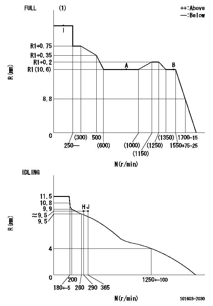
Injection quantity adjustment
Adjusting point
-
Rack position
10.6
Pump speed
r/min
900
900
900
Average injection quantity
mm3/st.
54.6
53
56.2
Max. variation between cylinders
%
0
-2.5
2.5
Basic
*
Fixing the rack
*
Standard for adjustment of the maximum variation between cylinders
*
Injection quantity adjustment_02
Adjusting point
H
Rack position
9.5+-0.5
Pump speed
r/min
290
290
290
Average injection quantity
mm3/st.
8
6.7
9.3
Max. variation between cylinders
%
0
-14
14
Fixing the rack
*
Standard for adjustment of the maximum variation between cylinders
*
Injection quantity adjustment_03
Adjusting point
A
Rack position
R1(10.6)
Pump speed
r/min
900
900
900
Average injection quantity
mm3/st.
54.6
53.6
55.6
Basic
*
Fixing the lever
*
Injection quantity adjustment_04
Adjusting point
B
Rack position
R1(10.6)
Pump speed
r/min
1500
1500
1500
Average injection quantity
mm3/st.
65.4
62.2
68.6
Fixing the lever
*
Timer adjustment
Pump speed
r/min
1350--
Advance angle
deg.
0
0
0
Remarks
Start
Start
Timer adjustment_02
Pump speed
r/min
1300
Advance angle
deg.
0.5
Timer adjustment_03
Pump speed
r/min
1500
Advance angle
deg.
3.5
3
4
Remarks
Finish
Finish
Test data Ex:
Governor adjustment
N:Pump speed
R:Rack position (mm)
(1)Torque cam stamping: T1
----------
T1=C78
----------
----------
T1=C78
----------
Speed control lever angle

F:Full speed
I:Idle
(1)Use the hole at R = aa
(2)Stopper bolt setting
----------
aa=35mm
----------
a=34deg+-5deg b=33deg+-3deg
----------
aa=35mm
----------
a=34deg+-5deg b=33deg+-3deg
Stop lever angle

N:Pump normal
S:Stop the pump.
(1)Stopper bolt setting
----------
----------
a=25deg+-5deg b=40deg+-5deg
----------
----------
a=25deg+-5deg b=40deg+-5deg
0000001501 ACS

(A) Set screw
(B) Push rod 1
(C) Push rod 2
(D) Cover
1. Aneroid compensator unit adjustment
(1)Select the push rod 2 to obtain L2.
(2)Screw in (A) to obtain L1.
2. Adjustment when mounting the governor.
(1)Set the speed of the pump to N1 r/min and fix the control lever at the full set position.
(2)Screw in the aneroid compensator to obtain the performance shown in the graph above.
(3)As there is hysterisis, measure when the absolute pressure drops.
(4)Hysterisis must not exceed rack position = h1.
----------
N1=900r/min L1=(1.5)mm L2=11+-0.5mm h1=0.15mm
----------
Ra=R1(10.6)mm Rb=R1-0.5mm Pa=84.5+-2.7kPa(634+-20mmHg) Pb=70.1+-0.7kPa(526+-5mmHg) Q1=54.6+-1cm3/1000st Q2=(40.4)+-1.6cm3/1000st
----------
N1=900r/min L1=(1.5)mm L2=11+-0.5mm h1=0.15mm
----------
Ra=R1(10.6)mm Rb=R1-0.5mm Pa=84.5+-2.7kPa(634+-20mmHg) Pb=70.1+-0.7kPa(526+-5mmHg) Q1=54.6+-1cm3/1000st Q2=(40.4)+-1.6cm3/1000st
0000001601 I/P WITH LOAD PLUNGER ADJ
Plunger assembly number: PL (stamping: ST)
1. Adjustment procedures
(1)Insert the pre-stroke adjusting shims L1 for each cylinder.
(2)Adjust injection quantity.(max. var. bet. cyl. idling a1, full a2)
(3)At basic point A, adjust so that the pre-stroke is L2.
(4)Reconfirm the injection quantity.
----------
PL=131154-0720 ST=A249 L1=1mm L2=3.6+-0.05mm a1=+-14% a2=+-2.5%
----------
----------
PL=131154-0720 ST=A249 L1=1mm L2=3.6+-0.05mm a1=+-14% a2=+-2.5%
----------
Timing setting

(1)Pump vertical direction
(2)Position of timer's threaded hole at No 1 cylinder's beginning of injection
(3)B.T.D.C.: aa
(4)-
----------
aa=12deg
----------
a=(60deg)
----------
aa=12deg
----------
a=(60deg)
Information:
Problem
Some remanufactured fuel injection pumps have been built with the control solenoid in the wrong position. If the solenoid is in the wrong position, the wiring harness may be impossible to connect to the solenoid due to interference of other components.The affected fuel pump part numbers are:
10R-7659 Unit Injection Hydraulic Pump and Mounting Gp
10R-7660 Unit Injection Hydraulic Pump and Mounting Gp
10R-7661 Unit Injection Hydraulic Pump and Mounting Gp
10R-7662 Fuel Pump Gp
20R-3815 Fuel Injection Pump GpSolution
Illustration 1 g06120812
View of the top of the 10R-7661 Unit Injection Hydraulic Pump and Mounting Gp and 10R-7662 Fuel Pump Gp.
(X) Pump center line
(Y) Acceptable solenoid connector orientation (—30 degrees to 30 degrees from pump center line)
Illustration 2 g06120817
View of the top of the 10R-7659 Unit Injection Hydraulic Pump and Mounting Gp, 10R-7660 Unit Injection Hydraulic Pump and Mounting Gp, and 20R-3815 Fuel Injection Pump Gp.
(X) Pump center line
(Z) Acceptable solenoid connector orientation (15 degrees to 45 degrees from pump center line)Check the fuel injection pump solenoid position before attempting to install the pump. Refer to Illustration 1 and Illustration 2. If the orientation of the connector on the solenoid is not within the acceptable range, return the faulty pump and replace the pump with the same part number.Note: Do not attempt to disassemble the fuel injection pump to reposition the solenoid.