Information injection-pump assembly
ZEXEL
101603-6750
1016036750

Rating:
Cross reference number
ZEXEL
101603-6750
1016036750
Zexel num
Bosch num
Firm num
Name
Calibration Data:
Adjustment conditions
Test oil
1404 Test oil ISO4113 or {SAEJ967d}
1404 Test oil ISO4113 or {SAEJ967d}
Test oil temperature
degC
40
40
45
Nozzle and nozzle holder
105780-8140
Bosch type code
EF8511/9A
Nozzle
105780-0000
Bosch type code
DN12SD12T
Nozzle holder
105780-2080
Bosch type code
EF8511/9
Opening pressure
MPa
17.2
Opening pressure
kgf/cm2
175
Injection pipe
Outer diameter - inner diameter - length (mm) mm 6-2-600
Outer diameter - inner diameter - length (mm) mm 6-2-600
Overflow valve
131424-5520
Overflow valve opening pressure
kPa
255
221
289
Overflow valve opening pressure
kgf/cm2
2.6
2.25
2.95
Tester oil delivery pressure
kPa
157
157
157
Tester oil delivery pressure
kgf/cm2
1.6
1.6
1.6
Direction of rotation (viewed from drive side)
Left L
Left L
Injection timing adjustment
Direction of rotation (viewed from drive side)
Left L
Left L
Injection order
1-5-3-6-
2-4
Pre-stroke
mm
4.2
4.15
4.25
Beginning of injection position
Governor side NO.1
Governor side NO.1
Difference between angles 1
Cal 1-5 deg. 60 59.5 60.5
Cal 1-5 deg. 60 59.5 60.5
Difference between angles 2
Cal 1-3 deg. 120 119.5 120.5
Cal 1-3 deg. 120 119.5 120.5
Difference between angles 3
Cal 1-6 deg. 180 179.5 180.5
Cal 1-6 deg. 180 179.5 180.5
Difference between angles 4
Cyl.1-2 deg. 240 239.5 240.5
Cyl.1-2 deg. 240 239.5 240.5
Difference between angles 5
Cal 1-4 deg. 300 299.5 300.5
Cal 1-4 deg. 300 299.5 300.5
Injection quantity adjustment
Adjusting point
A
Rack position
11.5
Pump speed
r/min
1400
1400
1400
Average injection quantity
mm3/st.
101.6
100.6
102.6
Max. variation between cylinders
%
0
-2.5
2.5
Basic
*
Fixing the lever
*
Injection quantity adjustment_02
Adjusting point
B
Rack position
8.3+-0.5
Pump speed
r/min
275
275
275
Average injection quantity
mm3/st.
12
10.5
13.5
Max. variation between cylinders
%
0
-15
15
Fixing the rack
*
Injection quantity adjustment_03
Adjusting point
C
Rack position
8+-0.5
Pump speed
r/min
350
350
350
Average injection quantity
mm3/st.
14.1
12.6
15.6
Fixing the rack
*
Timer adjustment
Pump speed
r/min
1050--
Advance angle
deg.
0
0
0
Remarks
Start
Start
Timer adjustment_02
Pump speed
r/min
1000
Advance angle
deg.
0.5
Timer adjustment_03
Pump speed
r/min
1400
Advance angle
deg.
2
1.5
2.5
Remarks
Finish
Finish
Test data Ex:
Governor adjustment
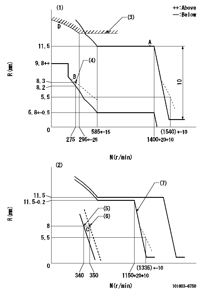
N:Pump speed
R:Rack position (mm)
(1)Adjust with speed control lever at full position (minimum-maximum speed specification)
(2)Adjust with the load control lever in the full position (variable speed specification).
(3)Excess fuel setting for starting: SXL
(4)Damper spring setting
(5)Main spring setting
(6)Set idle sub-spring
(7)When air cylinder is operating.
----------
SXL=12.5+-0.1mm
----------
----------
SXL=12.5+-0.1mm
----------
Speed control lever angle
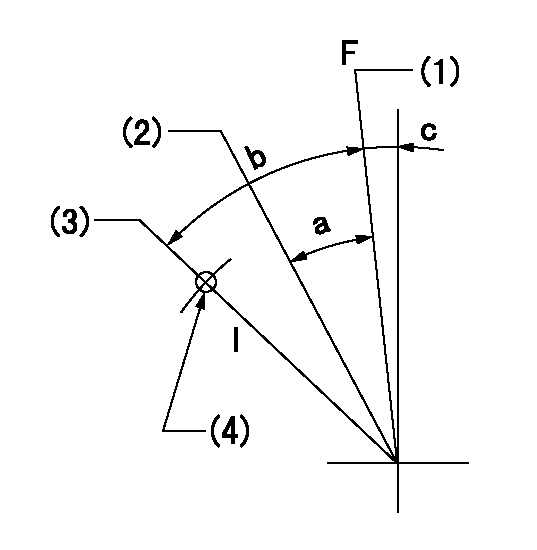
F:Full speed
I:Idle
(1)Pump speed = aa
(2)Pump speed = bb
(3)Pump speed cc
(4)Use the hole above R = dd
----------
aa=1400r/min bb=1150r/min cc=350r/min dd=190mm
----------
a=6deg+-5deg b=21deg+-5deg c=3deg+-5deg
----------
aa=1400r/min bb=1150r/min cc=350r/min dd=190mm
----------
a=6deg+-5deg b=21deg+-5deg c=3deg+-5deg
0000000901
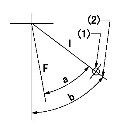
F:Full load
I:Idle
(1)Use the hole at R = aa
(2)Stopper bolt setting
----------
aa=70mm
----------
a=22deg+-3deg b=31.5deg+-5deg
----------
aa=70mm
----------
a=22deg+-3deg b=31.5deg+-5deg
Stop lever angle
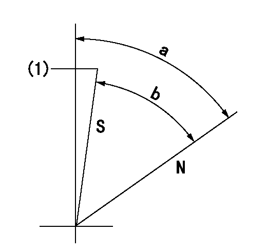
N:Pump normal
S:Stop the pump.
(1)Rack position = aa
----------
aa=5mm
----------
a=57deg+-5deg b=55.5deg+-5deg
----------
aa=5mm
----------
a=57deg+-5deg b=55.5deg+-5deg
0000001501 2-STAGE CHANGEOVER DEVICE

RFD governor 2 stage changeover mechanism adjustment outline
(A) Bolt
(B) bolt
(c) Nut
(D) Return spring
(E) Bolt
(F) Bolt
(G) Screw
(H) Bolt
(I) Load lever
(J) Speed lever
(K) Air cylinder
(M Air inlet
Figure 1 is only for reference. Lever shape, etc, may vary.
1. Minimum-maximum speed specification adjustment (when running)
(a) Without applying air to the air cylinder, loosen bolts (A) and (B).
(1)High speed return L setting
(a) In the speed range Nf~Nf - 300r/min, adjust using the speed adjusting bolt to determine the temporary beginning of high speed control speed.
(b) Determine the rack position in the vicinity of Rf using the full load lever.
(c) Increase speed and confirm return distance L.
(d) Adjust using the tension lever bolt to obtain L.
(2)Setting full load rack position Rf
(a) Move the load control lever to the full side.
(b) Adjust the full load adjusting bolt so that Rf can be obtained, then fix.
(3)Setting the beginning of high speed operation Nf
(a) Adjust using bolt (E) so that Nf can be obtained, and then fix.
(4)Idle control setting (Re, Ni, Rc)
(a) Set the speed at Ns + 200r/min and move the load control lever to the idle side.
(b) Fix the lever in the position where Re can be obtained.
(c) Next, decrease speed to Ni and screw in the idle spring.
(d) Adjust to obtain rack position Ri.
(e) Increase the speed and after confirming that the rack position is Re at Ns, set the speed at 0.
(f) Confirm protrusion position Rc at idle.
(5)Damper spring adjustment
(a) Increase speed and set the speed at the rack position Rd - 0.1 mm
(b) Set using the damper spring so that the rack position Rd can be obtained.
(c) When Rd is not specified, Rd = Ri - 0.5 mm.
(6)High speed droop confirmation
(a) Return the load control lever to the full load lever position.
(b) Increase the speed and confirm that Rf can be obtained at Nf r/min.
(c) Confirm that speed is Nh at rack position Rh.
2. Variable speed specification adjustment (at operation)
(a) Remove return spring (D).
(b) Apply air pressure of 245~294 kPa {2.5~3 kg/cm2} to the air cylinder.
(c) Perform the following adjustment in this condition.
(1)Setting full load rack position Rf'
(a) Pull the load lever to the idle side.
(b) Obtain rack position Rf' using the nut (C). (Pump speed is Nf'-50 r/min.)
(2)Setting full speed Nf'
(a) Adjust using bolt (B) so that Nf can be obtained, and then fix.
(3)Low speed side setting
(a) At 350r/min, set bolt (F) at beginning of governor operation position, then fix.
3. Bolt (A) adjustment
(1)Install return spring (D) and perform the adjustments below at air pressure 0.
(a) Set at speed Nf using bolt (E).
(b) Screw in bolt (A).
(c) Screw in 1 more turn from the speed lever contact position
(d) Fix bolt (A).
(e) At this time confirm that the air cylinder's shaft moves approximately 1 mm towards the governor.
4. Lever operation confirmation using the air cylinder
(1)Apply 588 kPa {6 kg/cm2} air pressure to the air cylinder.
(2)Confirm that the cylinder piston is moved 50 mm by the spring (D).
----------
----------
----------
----------
0000001601 MICRO SWITCH
Adjustment of the micro-switch
Adjust the bolt to obtain the following lever position when the micro-switch is ON.
(1)Speed N1
(2)Rack position Ra
----------
N1=400r/min Ra=8mm
----------
----------
N1=400r/min Ra=8mm
----------
Timing setting

(1)Pump vertical direction
(2)Position of timer's tooth at No 1 cylinder's beginning of injection
(3)B.T.D.C.: aa
(4)-
----------
aa=14deg
----------
a=(1deg)
----------
aa=14deg
----------
a=(1deg)
Information:
The lubrication system consists of a sump (oil pan), oil pump, oil cooler and oil filter. The engine contains an oil manifold and oil passages to direct lubricant to the various components.The oil pump draws lubricant from the sump and forces it through the oil cooler, oil filter, and then into the oil manifold. Oil flows through connecting passages to lubricate the engine components. A regulating valve in the pump body controls the maximum pressure of the oil from the pump. When the engine is started, the lubricating oil in the oil pan is cool (thick). This cool viscous oil does not flow immediately through the oil cooler and oil filter. This cool oil forces bypass valves, in the oil cooler and oil filter base, to open allowing an unrestricted oil to flow through the engine.As oil temperature increases, oil viscosity and pressure decrease and the oil filter bypass valve closes. Now, only filtered oil is delivered to the engine components. Oil temperature continues to increase and the oil cooler bypass valve closes. Oil now flows through the oil cooler and oil filter before reaching the engine components.A contaminated or restricted oil filter element will not prevent lubricating oil from being delivered to the engine components. The oil filter bypass valve will open, allowing oil to bypass the element.An oil manifold, cast into the cylinder block, directs lubricant to the main bearings, valve rocker arm shafts, camshaft journals, and the camshaft idler (drive) gears.Oil spray orifices in the cylinder block spray oil on the underside of the pistons. This cools the pistons and provides lubricant for the piston pins, cylinder walls and piston rings.The connecting rod bearings receive oil through drilled passages in the crankshaft between the main bearing journals and connecting rod journals.When the engine is warm and running at rated speed, the oil pressure gauge should register in the "operating range". A lower pressure reading is normal at idling speeds.Many engines are equipped with an auxiliary or remote mounted bypass filter system. This system must be connected so part of the oil continuously circulates through the bypass filter, from the crankcase lubricating oil pump. An orifice on the outlet or clean side of the filter restricts the flow of oil through the bypass filter so full oil pressure is available to all parts of the engine. Filtered oil from the bypass filter is returned to the crankcase sump. Because of the additional oil capacity, extended change intervals can be established. See Lubrication Chart. The Bypass filter should never be used in place of the factory installed full flow filter.