Information injection-pump assembly
BOSCH
9 400 615 141
9400615141
ZEXEL
101603-6690
1016036690
MITSUBISHI
ME059795
me059795
Rating:
Service parts 101603-6690 INJECTION-PUMP ASSEMBLY:
1.
_
7.
COUPLING PLATE
8.
_
9.
_
11.
Nozzle and Holder
12.
Open Pre:MPa(Kqf/cm2)
21.6(220)

15.
NOZZLE SET
Cross reference number
BOSCH
9 400 615 141
9400615141
ZEXEL
101603-6690
1016036690
MITSUBISHI
ME059795
me059795
Zexel num
Bosch num
Firm num
Name
101603-6690
9 400 615 141
ME059795 MITSUBISHI
INJECTION-PUMP ASSEMBLY
6D22 K 14BF INJECTION PUMP ASSY PE6AD PE
6D22 K 14BF INJECTION PUMP ASSY PE6AD PE
Calibration Data:
Adjustment conditions
Test oil
1404 Test oil ISO4113 or {SAEJ967d}
1404 Test oil ISO4113 or {SAEJ967d}
Test oil temperature
degC
40
40
45
Nozzle and nozzle holder
105780-8140
Bosch type code
EF8511/9A
Nozzle
105780-0000
Bosch type code
DN12SD12T
Nozzle holder
105780-2080
Bosch type code
EF8511/9
Opening pressure
MPa
17.2
Opening pressure
kgf/cm2
175
Injection pipe
Outer diameter - inner diameter - length (mm) mm 6-2-600
Outer diameter - inner diameter - length (mm) mm 6-2-600
Overflow valve
131424-5120
Overflow valve opening pressure
kPa
255
221
289
Overflow valve opening pressure
kgf/cm2
2.6
2.25
2.95
Tester oil delivery pressure
kPa
157
157
157
Tester oil delivery pressure
kgf/cm2
1.6
1.6
1.6
Direction of rotation (viewed from drive side)
Right R
Right R
Injection timing adjustment
Direction of rotation (viewed from drive side)
Right R
Right R
Injection order
1-5-3-6-
2-4
Pre-stroke
mm
4.5
4.45
4.55
Beginning of injection position
Governor side NO.1
Governor side NO.1
Difference between angles 1
Cal 1-5 deg. 60 59.5 60.5
Cal 1-5 deg. 60 59.5 60.5
Difference between angles 2
Cal 1-3 deg. 120 119.5 120.5
Cal 1-3 deg. 120 119.5 120.5
Difference between angles 3
Cal 1-6 deg. 180 179.5 180.5
Cal 1-6 deg. 180 179.5 180.5
Difference between angles 4
Cyl.1-2 deg. 240 239.5 240.5
Cyl.1-2 deg. 240 239.5 240.5
Difference between angles 5
Cal 1-4 deg. 300 299.5 300.5
Cal 1-4 deg. 300 299.5 300.5
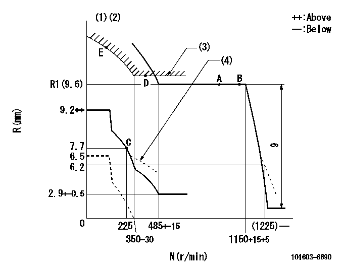
Injection quantity adjustment
Adjusting point
-
Rack position
9.6
Pump speed
r/min
700
700
700
Each cylinder's injection qty
mm3/st.
112
108.6
115.4
Basic
*
Fixing the rack
*
Standard for adjustment of the maximum variation between cylinders
*
Injection quantity adjustment_02
Adjusting point
C
Rack position
7.7+-0.5
Pump speed
r/min
225
225
225
Each cylinder's injection qty
mm3/st.
18.5
15.7
21.3
Fixing the rack
*
Standard for adjustment of the maximum variation between cylinders
*
Injection quantity adjustment_03
Adjusting point
A
Rack position
R1(9.6)
Pump speed
r/min
700
700
700
Average injection quantity
mm3/st.
112
111
113
Basic
*
Fixing the lever
*
Injection quantity adjustment_04
Adjusting point
B
Rack position
R1(9.6)
Pump speed
r/min
1100
1100
1100
Average injection quantity
mm3/st.
112
109.5
114.5
Difference in delivery
mm3/st.
9
9
9
Fixing the lever
*
Injection quantity adjustment_05
Adjusting point
E
Rack position
-
Pump speed
r/min
100
100
100
Average injection quantity
mm3/st.
170
130
210
Fixing the lever
*
Remarks
After startup boost setting
After startup boost setting
Timer adjustment
Pump speed
r/min
850--
Advance angle
deg.
0
0
0
Remarks
Start
Start
Timer adjustment_02
Pump speed
r/min
800
Advance angle
deg.
0.5
Timer adjustment_03
Pump speed
r/min
900
Advance angle
deg.
0.9
0.4
1.4
Timer adjustment_04
Pump speed
r/min
1150
Advance angle
deg.
3
2.5
3.5
Timer adjustment_05
Pump speed
r/min
-
Advance angle
deg.
4
3
5
Remarks
Measure the actual speed, stop
Measure the actual speed, stop
Test data Ex:
Governor adjustment
N:Pump speed
R:Rack position (mm)
(1)Lever ratio: RT
(2)Target shim dimension: TH
(3)Excess fuel setting for starting: SXL
(4)Damper spring setting: DL
----------
RT=1 TH=2.9mm SXL=11.6+-0.1mm DL=6.7-0.2mm
----------
----------
RT=1 TH=2.9mm SXL=11.6+-0.1mm DL=6.7-0.2mm
----------
Speed control lever angle

F:Full speed
----------
----------
a=4deg+-5deg
----------
----------
a=4deg+-5deg
0000000901
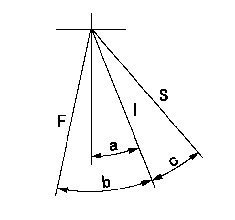
F:Full load
I:Idle
S:Stop
----------
----------
a=21deg+-5deg b=24.5deg+-3deg c=13deg+-3deg
----------
----------
a=21deg+-5deg b=24.5deg+-3deg c=13deg+-3deg
Stop lever angle
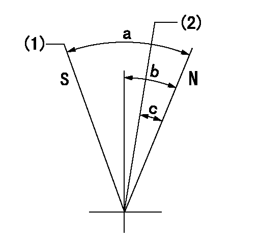
N:Pump normal
S:Stop the pump.
(1)Rack position = aa
(2)Rack position bb
----------
aa=2.5mm bb=21mm
----------
a=71deg+-5deg b=12deg+-5deg c=(9.5deg)
----------
aa=2.5mm bb=21mm
----------
a=71deg+-5deg b=12deg+-5deg c=(9.5deg)
0000001501 MICRO SWITCH
Adjustment of the micro-switch
Adjust the bolt to obtain the following lever position when the micro-switch is ON.
(1)Speed N1
(2)Rack position Ra
----------
N1=325+-5r/min Ra=7mm
----------
----------
N1=325+-5r/min Ra=7mm
----------
Timing setting

(1)Pump vertical direction
(2)Coupling's key groove position at No 1 cylinder's beginning of injection
(3)-
(4)-
----------
----------
a=(7deg)
----------
----------
a=(7deg)
Information:
CLEANING ELEMENT WITH AIRCLEANING WITH WATER: Using clean water, at a pressure not to exceed 40 PSI, proceed as follows:Direct water at an angle against the inside (engine side) of the element to loosen any imbedded dirt. Best results can be obtained by using a water hose without a nozzle and moving it so that water is directed at an angle along the complete length of each pleat. Wash off loose dirt by directing water against the outside of the element. Repeat this procedure until the element is clean. Make certain that no dirt is on the engine side of the element, and thoroughly dry the element before installing it.
CLEANING ELEMENT WITH WATERCLEANING WITH DETERGENT: Some oily and/or sooty deposits can be removed by washing the element in a solution of warm water and a good household non-sudsing detergent. Rinse with clean water and thoroughly dry the element before installing it.
WASHING ELEMENT WITH DETERGENTINSPECTING ELEMENT:1. Hold a lighted electric bulb inside the dried element and carefully inspect the element for tiny, pinpoints of light. Any light showing indicates a pleat has ruptured and will tear with further use. Discard the element.2. Wrap usable elements in sealed plastic bags.3. Store the wrapped element in a dry, clean place.
INSPECTING ELEMENTWhen equipped with oil bath type air cleaners, accumulation of dirt and/or oil in the air cleaner outlet pipe is an indication the air cleaner is not being serviced or functioning properly. Refer to manufacturer's recommendations for servicing.Valve Lash Setting
Check Valve Lash Setting With Engine Stopped:1. Remove the flywheel timing cover from the flywheel housing. Rotate the engine flywheel in direction of engine rotation, so the flywheel timing pointer is at the TC 1-6 cyl. mark on the flywheel. Remove the bolt from the flywheel timing hole and insert timing bolt (long bolt which fastens cover to flywheel). 2. Remove the valve cover and observe the positions of the No. 1 and No. 6 cylinder valves and the camshaft lobes to determine which cylinder is sealed for compression.3. Turn adjusting screw counterclockwise 2 clicks or more to provide clearance between rocker assembly and valve.4. Turn adjusting screw clockwise to obtain zero lash. There should be no free rocker movement or adjusting screw button lateral movement.
VALVE ADJUSTMENT The adjusting screw button can still be rotated by finger pressure even when it is in contact with valve stem and clearance is zero. Turning the adjusting screw clockwise beyond this point will force the valve off its seat, and final lash setting will be incorrect.
VALVE CLEARANCE SETTINGS5. Turn adjustment screw counterclockwise ten clicks (.020 in.; 0,50 mm) for exhaust valves and four clicks (.008 in.; 0,20 mm) for inlet valves. One click is equal to .002 in. (0,050 mm). All exhaust and inlet valve clearance can be adjusted by positioning the flywheel only twice. After adjusting half of the valves, rotate the engine 360° in direction of normal rotation and adjust the remaining half. If No. 1 cylinder is in compression, adjust the inlet
Have questions with 101603-6690?
Group cross 101603-6690 ZEXEL
Mitsubishi
101603-6690
9 400 615 141
ME059795
INJECTION-PUMP ASSEMBLY
6D22
6D22