Information injection-pump assembly
ZEXEL
101603-6181
1016036181

Rating:
Cross reference number
ZEXEL
101603-6181
1016036181
Zexel num
Bosch num
Firm num
Name
Calibration Data:
Adjustment conditions
Test oil
1404 Test oil ISO4113 or {SAEJ967d}
1404 Test oil ISO4113 or {SAEJ967d}
Test oil temperature
degC
40
40
45
Nozzle and nozzle holder
105780-8140
Bosch type code
EF8511/9A
Nozzle
105780-0000
Bosch type code
DN12SD12T
Nozzle holder
105780-2080
Bosch type code
EF8511/9
Opening pressure
MPa
17.2
Opening pressure
kgf/cm2
175
Injection pipe
Outer diameter - inner diameter - length (mm) mm 6-2-600
Outer diameter - inner diameter - length (mm) mm 6-2-600
Overflow valve
131424-5520
Overflow valve opening pressure
kPa
255
221
289
Overflow valve opening pressure
kgf/cm2
2.6
2.25
2.95
Tester oil delivery pressure
kPa
157
157
157
Tester oil delivery pressure
kgf/cm2
1.6
1.6
1.6
Direction of rotation (viewed from drive side)
Left L
Left L
Injection timing adjustment
Direction of rotation (viewed from drive side)
Left L
Left L
Injection order
1-5-3-6-
2-4
Pre-stroke
mm
3
2.95
3.05
Beginning of injection position
Governor side NO.1
Governor side NO.1
Difference between angles 1
Cal 1-5 deg. 60 59.5 60.5
Cal 1-5 deg. 60 59.5 60.5
Difference between angles 2
Cal 1-3 deg. 120 119.5 120.5
Cal 1-3 deg. 120 119.5 120.5
Difference between angles 3
Cal 1-6 deg. 180 179.5 180.5
Cal 1-6 deg. 180 179.5 180.5
Difference between angles 4
Cyl.1-2 deg. 240 239.5 240.5
Cyl.1-2 deg. 240 239.5 240.5
Difference between angles 5
Cal 1-4 deg. 300 299.5 300.5
Cal 1-4 deg. 300 299.5 300.5
Injection quantity adjustment
Adjusting point
-
Rack position
12.1
Pump speed
r/min
800
800
800
Each cylinder's injection qty
mm3/st.
88
85.4
90.6
Basic
*
Fixing the rack
*
Standard for adjustment of the maximum variation between cylinders
*
Injection quantity adjustment_02
Adjusting point
H
Rack position
9.5+-0.5
Pump speed
r/min
275
275
275
Each cylinder's injection qty
mm3/st.
10.5
9
12
Fixing the rack
*
Standard for adjustment of the maximum variation between cylinders
*
Injection quantity adjustment_03
Adjusting point
A
Rack position
R1(12.1)
Pump speed
r/min
800
800
800
Average injection quantity
mm3/st.
88
87
89
Basic
*
Fixing the lever
*
Boost pressure
kPa
61.3
61.3
Boost pressure
mmHg
460
460
Injection quantity adjustment_04
Adjusting point
C
Rack position
(R1-0.8)
Pump speed
r/min
600
600
600
Average injection quantity
mm3/st.
67
65
69
Fixing the lever
*
Boost pressure
kPa
28
28
28
Boost pressure
mmHg
210
210
210
Injection quantity adjustment_05
Adjusting point
I
Rack position
13.9+-0.
5
Pump speed
r/min
100
100
100
Average injection quantity
mm3/st.
90
70
110
Fixing the lever
*
Rack limit
*
Boost compensator adjustment
Pump speed
r/min
600
600
600
Rack position
R1-1.1
Boost pressure
kPa
22
22
22
Boost pressure
mmHg
165
165
165
Boost compensator adjustment_02
Pump speed
r/min
600
600
600
Rack position
(R1-0.8)
Boost pressure
kPa
28
26.7
29.3
Boost pressure
mmHg
210
200
220
Boost compensator adjustment_03
Pump speed
r/min
600
600
600
Rack position
R1(12.1)
Boost pressure
kPa
48
41.3
54.7
Boost pressure
mmHg
360
310
410
Timer adjustment
Pump speed
r/min
1250--
Advance angle
deg.
0
0
0
Remarks
Start
Start
Timer adjustment_02
Pump speed
r/min
1200
Advance angle
deg.
0.5
Timer adjustment_03
Pump speed
r/min
1300
Advance angle
deg.
1.6
1.1
2.1
Timer adjustment_04
Pump speed
r/min
1400
Advance angle
deg.
3.5
3
4
Remarks
Finish
Finish
Test data Ex:
Governor adjustment
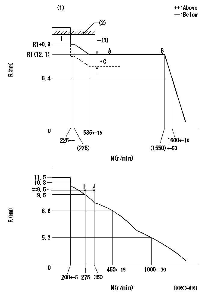
N:Pump speed
R:Rack position (mm)
(1)Torque cam stamping: T1
(2)RACK LIMIT
(3)Boost compensator stroke: BCL
----------
T1=B45 BCL=1.1+-0.1mm
----------
----------
T1=B45 BCL=1.1+-0.1mm
----------
Speed control lever angle

F:Full speed
I:Idle
(1)Stopper bolt set position 'H'
----------
----------
a=10deg+-5deg b=(46deg)+-3deg
----------
----------
a=10deg+-5deg b=(46deg)+-3deg
Stop lever angle

N:Engine manufacturer's normal use
S:Stop the pump.
(1)Set the stopper bolt at speed = aa and rack position = bb and confirm non-injection.
(2)After setting the stopper bolt, confirm non-injection at speed = dd. Rack position = cc.
(3)Rack position = approximately ee.
(4)Free (at shipping)
----------
aa=1550r/min bb=(7.5)mm cc=(9)mm dd=275r/min ee=17.4mm
----------
a=38.5deg+-5deg b=(27deg) c=17deg+-5deg
----------
aa=1550r/min bb=(7.5)mm cc=(9)mm dd=275r/min ee=17.4mm
----------
a=38.5deg+-5deg b=(27deg) c=17deg+-5deg
0000001501 MICRO SWITCH
Adjustment of the micro-switch
Adjust the bolt to obtain the following lever position when the micro-switch is ON.
(1)Speed N1
(2)Rack position Ra
----------
N1=400+-5r/min Ra=9.2mm
----------
----------
N1=400+-5r/min Ra=9.2mm
----------
Timing setting

(1)Pump vertical direction
(2)Position of timer's tooth at No 1 cylinder's beginning of injection
(3)B.T.D.C.: aa
(4)-
----------
aa=16deg
----------
a=(1deg)
----------
aa=16deg
----------
a=(1deg)
Information:
Repeat Steps 4 through 6 to remove (bleed) air from the rear table lift cylinder (not shown).
Open (CCW) hand pump control knob (11) to completely lower the DPF cleaner table. Close (CW) the hand pump control knob.
Illustration 38 g02728258
(28) Hydraulic Oil Level 51 to 102 mm (2.0 to 4.0 inch)
Check the oil level in the pump reservoir. Remove fill cap (13) located on the end cap of the hand pump. Hydraulic oil level (28) should be 51 to 102 mm (2.0 to 4.0 inch) from the bottom of the fill hole. Add high-grade hydraulic oil, if needed.Note: A clean wire tie can be used as a dipstick to measure the hydraulic oil level in the pump reservoir.Troubleshooting Guide
Table 3
Symptom Solution
Air dryer desiccant is a pinkish color. 1. Replace or regenerate the desiccant. Refer to ""Maintenance Section"".
Bursting does not occur. 1. Check display screen for error message.
2. Check power connection to burst valve solenoid.
Cabinet doors do not close correctly. 1. Look for damaged door hinges, seals, and latches.
2. Verify that vehicle sensors have been removed from DPF.
Cabinet doors open during burst process. 1. Verify that doors are correctly latched.
2. Look for damage to door latches.
3. Check seals between DPF and adapters.
Clamping force cannot be obtained. 1. Look for hydraulic fluid leaks.
2. Check fluid level in hydraulic pump. Refer to ""Maintenance Section"".
Clamping force does not hold. 1. Upon initial clamping, it is possible for clamp load to drop
689 to 1379 kPa (99.9 to 200.0 psi) within the first minute, due to temperature effects. After reclamping, the drop should be virtually zero.
2. Look for hydraulic fluid leaks.
Display screen is blank. 1. Verify that machine is ON, plugged into an outlet, and power is available to the outlet.
2. Reset circuit breakers located on left side of control cabinet.
DPF does not line up correctly on the table. 1. Verify that correct adapters are being used.
2. Verify DPF is correctly seated on to lower adapter.
DPF is damaged after cleaning process. 1. Check DPFs for damage before cleaning.
2. Look for damage on adapters.
3. Verify that correct cleaning protocol was entered into machine.
DPF is not cleaned. 1. Check orientation of DPF. Refer to ""General Information"" Section.
2. Verify that correct cleaning protocol was entered into machine.
3. Look for other DPF conditions that may prevent successful cleaning.