Information injection-pump assembly
ZEXEL
101603-6170
1016036170
MITSUBISHI
ME035584
me035584
Rating:
Cross reference number
ZEXEL
101603-6170
1016036170
MITSUBISHI
ME035584
me035584
Zexel num
Bosch num
Firm num
Name
101603-6170
ME035584 MITSUBISHI
INJECTION-PUMP ASSEMBLY
6D15 * K
6D15 * K
Calibration Data:
Adjustment conditions
Test oil
1404 Test oil ISO4113 or {SAEJ967d}
1404 Test oil ISO4113 or {SAEJ967d}
Test oil temperature
degC
40
40
45
Nozzle and nozzle holder
105780-8140
Bosch type code
EF8511/9A
Nozzle
105780-0000
Bosch type code
DN12SD12T
Nozzle holder
105780-2080
Bosch type code
EF8511/9
Opening pressure
MPa
17.2
Opening pressure
kgf/cm2
175
Injection pipe
Outer diameter - inner diameter - length (mm) mm 6-2-600
Outer diameter - inner diameter - length (mm) mm 6-2-600
Overflow valve
131424-5520
Overflow valve opening pressure
kPa
255
221
289
Overflow valve opening pressure
kgf/cm2
2.6
2.25
2.95
Tester oil delivery pressure
kPa
157
157
157
Tester oil delivery pressure
kgf/cm2
1.6
1.6
1.6
Direction of rotation (viewed from drive side)
Left L
Left L
Injection timing adjustment
Direction of rotation (viewed from drive side)
Left L
Left L
Injection order
1-5-3-6-
2-4
Pre-stroke
mm
3.6
3.55
3.65
Beginning of injection position
Governor side NO.1
Governor side NO.1
Difference between angles 1
Cal 1-5 deg. 60 59.5 60.5
Cal 1-5 deg. 60 59.5 60.5
Difference between angles 2
Cal 1-3 deg. 120 119.5 120.5
Cal 1-3 deg. 120 119.5 120.5
Difference between angles 3
Cal 1-6 deg. 180 179.5 180.5
Cal 1-6 deg. 180 179.5 180.5
Difference between angles 4
Cyl.1-2 deg. 240 239.5 240.5
Cyl.1-2 deg. 240 239.5 240.5
Difference between angles 5
Cal 1-4 deg. 300 299.5 300.5
Cal 1-4 deg. 300 299.5 300.5
Injection quantity adjustment
Adjusting point
-
Rack position
11
Pump speed
r/min
850
850
850
Each cylinder's injection qty
mm3/st.
60
58.1
61.9
Basic
*
Fixing the rack
*
Standard for adjustment of the maximum variation between cylinders
*
Injection quantity adjustment_02
Adjusting point
-
Rack position
10+-0.5
Pump speed
r/min
275
275
275
Each cylinder's injection qty
mm3/st.
10
8.9
11.1
Fixing the rack
*
Standard for adjustment of the maximum variation between cylinders
*
Remarks
Adjust only variation between cylinders; adjust governor according to governor specifications.
Adjust only variation between cylinders; adjust governor according to governor specifications.
Injection quantity adjustment_03
Adjusting point
A
Rack position
R1(11)
Pump speed
r/min
850
850
850
Average injection quantity
mm3/st.
60
59
61
Basic
*
Fixing the lever
*
Injection quantity adjustment_04
Adjusting point
B
Rack position
R1+0.4
Pump speed
r/min
1450
1450
1450
Average injection quantity
mm3/st.
76.5
72.5
80.5
Fixing the lever
*
Injection quantity adjustment_05
Adjusting point
E
Rack position
-
Pump speed
r/min
100
100
100
Average injection quantity
mm3/st.
70
30
110
Fixing the lever
*
Remarks
After startup boost setting
After startup boost setting
Timer adjustment
Pump speed
r/min
1250--
Advance angle
deg.
0
0
0
Remarks
Start
Start
Timer adjustment_02
Pump speed
r/min
1200
Advance angle
deg.
0.5
Timer adjustment_03
Pump speed
r/min
1350
Advance angle
deg.
2.4
1.9
2.9
Timer adjustment_04
Pump speed
r/min
1500
Advance angle
deg.
5
4.5
5.5
Remarks
Finish
Finish
Test data Ex:
Governor adjustment
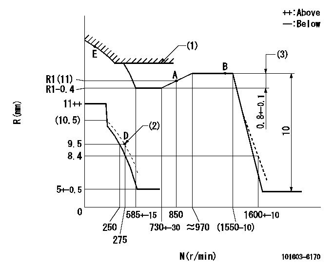
N:Pump speed
R:Rack position (mm)
(1)Excess fuel setting for starting: SXL
(2)Damper spring setting
(3)Rack difference between N = N1 and N = N2
----------
SXL=R1(11)+2+1.8mm N1=1450r/min N2=600r/min
----------
----------
SXL=R1(11)+2+1.8mm N1=1450r/min N2=600r/min
----------
Speed control lever angle

F:Full speed
----------
----------
a=13deg+-5deg
----------
----------
a=13deg+-5deg
0000000901
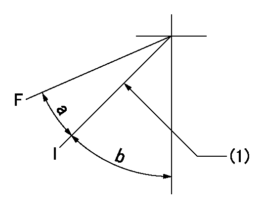
F:Full load
I:Idle
(1)Stopper bolt setting
----------
----------
a=20.5deg+-3deg b=30deg+-5deg
----------
----------
a=20.5deg+-3deg b=30deg+-5deg
Stop lever angle
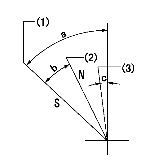
N:Engine manufacturer's normal use
S:Stop the pump.
(1)Rack position = aa
(2)Rack position bb
(3)Free (at shipping)
----------
aa=7-0.5mm bb=13.5mm
----------
a=55.5deg+7deg-5deg b=21.5deg+-5deg c=(1deg)
----------
aa=7-0.5mm bb=13.5mm
----------
a=55.5deg+7deg-5deg b=21.5deg+-5deg c=(1deg)
0000001501 MICRO SWITCH
Adjustment of the micro-switch
Adjust the bolt to obtain the following lever position when the micro-switch is ON.
(1)Speed N1
(2)Rack position Ra
----------
N1=400+-5r/min Ra=9.2mm
----------
----------
N1=400+-5r/min Ra=9.2mm
----------
Timing setting

(1)Pump vertical direction
(2)Position of timer's tooth at No 1 cylinder's beginning of injection
(3)B.T.D.C.: aa
(4)-
----------
aa=12deg
----------
a=(1deg)
----------
aa=12deg
----------
a=(1deg)
Information:
Introduction
This Special Instruction provides information in order to prolong the life of the cutting bits on the PM-465 rotor. An additional spray nozzle was added to the left side of the chamber.Rework Procedure
Table 1
Required Parts
Quantity Part Number Description
1 211-8607 Tube
1 211-8604 Plate
1 1G-6699 Adapter
1 1G-8270 Nozzle Body
2 5D-1026 Hose Clamp
1000 mm (39 inch) 5P-1690 Hose
1 081-2963 Cap
1 081-2965 Seal
1 115-9969 Male Connector
1 115-9970 Male Connector
1 212-0911 Nozzle
Illustration 1 g00853436
(A) 573 mm (22.56 inches) (B) 102.5 mm (4 inches) (C) 150 mm (5.91 inches)
Remove 142-7461 Plate (1) from the chamber.
Relocate the 142-7461 Plate (1) .
The new location of the 142-7461 Plate (1) should measure 150 mm (5.91 inches) (C) from the top of the chamber. The center of the 142-7461 Plate should remain at 573 mm (22.56 inches) (A) .
Cut a slot in the left side of the chamber that is 40 mm (1.57 inch) by 85 mm (3.35 inch). The center of the slot should measure 102.5 mm (4 inches) from the top (B) of the chamber and 573 mm (22.56 inches) from the front (A) of the chamber. Refer to Illustration 1.
Illustration 2 g00853889
Weld the 211-8604 Plate (2) in the slot. The plate should be flush with the inside of the chamber. Face the open end of the plate downward in the slot.
Illustration 3 g00853468
Illustration 4 g00853890
(D) 20 mm (0.79 inch) (E) 8.5 mm (0.33 inch)
Weld a 211-8607 Tube (3) onto the side of the chamber. Position the bottom of the tube 20 mm (0.79 inch) (D) from the bottom of the slot and 8.5 mm (0.33 inch) (E) to the right of the slot. Refer to Illustration 4.
Illustration 5 g00853470
Remove hose assembly (4) from the nozzle (5) that is located near the left side of the chamber.
Replace connector (6) with 115-9970 Male Connector .
Illustration 6 g00863254
Use the following parts in order to assemble a new nozzle: 115-9969 Male Connector (7), 1G-6699 Adapter (8), 1G-8270 Nozzle Body (9), 212-0911 Nozzle (10), 081-2965 Seal (11) and 081-2963 Cap (12) .
Illustration 7 g00853509
Place the new nozzle assembly in tube (13) that is located on the side of the chamber.Note: The flat spray pattern of the nozzle should be parallel to the slot.
Connect the two nozzles with a 5P-1690 Hose . Use two 5D-1026 Hose Clamps in order to secure the hose to the nozzles.
Have questions with 101603-6170?
Group cross 101603-6170 ZEXEL
Mitsubishi
101603-6170
ME035584
INJECTION-PUMP ASSEMBLY
6D15
6D15