Information injection-pump assembly
BOSCH
9 400 615 113
9400615113
ZEXEL
101603-6150
1016036150
MITSUBISHI
ME032909
me032909

Rating:
Service parts 101603-6150 INJECTION-PUMP ASSEMBLY:
1.
_
6.
COUPLING PLATE
7.
COUPLING PLATE
8.
_
9.
_
10.
NOZZLE AND HOLDER ASSY
11.
Nozzle and Holder
12.
Open Pre:MPa(Kqf/cm2)
13.
NOZZLE-HOLDER
14.
NOZZLE
15.
NOZZLE SET
Include in #1:
101603-6150
as INJECTION-PUMP ASSEMBLY
Include in #2:
104748-1713
as _
Cross reference number
BOSCH
9 400 615 113
9400615113
ZEXEL
101603-6150
1016036150
MITSUBISHI
ME032909
me032909
Zexel num
Bosch num
Firm num
Name
101603-6150
9 400 615 113
ME032909 MITSUBISHI
INJECTION-PUMP ASSEMBLY
6D15 K 14BE INJECTION PUMP ASSY PE6A PE
6D15 K 14BE INJECTION PUMP ASSY PE6A PE
Calibration Data:
Adjustment conditions
Test oil
1404 Test oil ISO4113 or {SAEJ967d}
1404 Test oil ISO4113 or {SAEJ967d}
Test oil temperature
degC
40
40
45
Nozzle and nozzle holder
105780-8140
Bosch type code
EF8511/9A
Nozzle
105780-0000
Bosch type code
DN12SD12T
Nozzle holder
105780-2080
Bosch type code
EF8511/9
Opening pressure
MPa
17.2
Opening pressure
kgf/cm2
175
Injection pipe
Outer diameter - inner diameter - length (mm) mm 6-2-600
Outer diameter - inner diameter - length (mm) mm 6-2-600
Overflow valve
131424-3720
Overflow valve opening pressure
kPa
255
221
289
Overflow valve opening pressure
kgf/cm2
2.6
2.25
2.95
Tester oil delivery pressure
kPa
157
157
157
Tester oil delivery pressure
kgf/cm2
1.6
1.6
1.6
Direction of rotation (viewed from drive side)
Left L
Left L
Injection timing adjustment
Direction of rotation (viewed from drive side)
Left L
Left L
Injection order
1-5-3-6-
2-4
Pre-stroke
mm
3.3
3.25
3.35
Beginning of injection position
Governor side NO.1
Governor side NO.1
Difference between angles 1
Cal 1-5 deg. 60 59.5 60.5
Cal 1-5 deg. 60 59.5 60.5
Difference between angles 2
Cal 1-3 deg. 120 119.5 120.5
Cal 1-3 deg. 120 119.5 120.5
Difference between angles 3
Cal 1-6 deg. 180 179.5 180.5
Cal 1-6 deg. 180 179.5 180.5
Difference between angles 4
Cyl.1-2 deg. 240 239.5 240.5
Cyl.1-2 deg. 240 239.5 240.5
Difference between angles 5
Cal 1-4 deg. 300 299.5 300.5
Cal 1-4 deg. 300 299.5 300.5
Injection quantity adjustment
Adjusting point
-
Rack position
11.5
Pump speed
r/min
850
850
850
Each cylinder's injection qty
mm3/st.
61.5
59.7
63.3
Basic
*
Fixing the rack
*
Standard for adjustment of the maximum variation between cylinders
*
Injection quantity adjustment_02
Adjusting point
C
Rack position
9.7+-0.5
Pump speed
r/min
275
275
275
Each cylinder's injection qty
mm3/st.
10.5
9
12
Fixing the rack
*
Standard for adjustment of the maximum variation between cylinders
*
Injection quantity adjustment_03
Adjusting point
A
Rack position
R1(11.5)
Pump speed
r/min
850
850
850
Average injection quantity
mm3/st.
61.5
60.5
62.5
Fixing the lever
*
Injection quantity adjustment_04
Adjusting point
B
Rack position
R1(11.5)
Pump speed
r/min
1500
1500
1500
Average injection quantity
mm3/st.
65.8
63.1
68.5
Difference in delivery
mm3/st.
5.4
5.4
5.4
Fixing the lever
*
Timer adjustment
Pump speed
r/min
850+-50
Advance angle
deg.
0
0
0
Remarks
Start
Start
Timer adjustment_02
Pump speed
r/min
1200
Advance angle
deg.
2.6
2.1
3.1
Timer adjustment_03
Pump speed
r/min
1500
Advance angle
deg.
5.5
5
6
Remarks
Finish
Finish
Test data Ex:
Governor adjustment
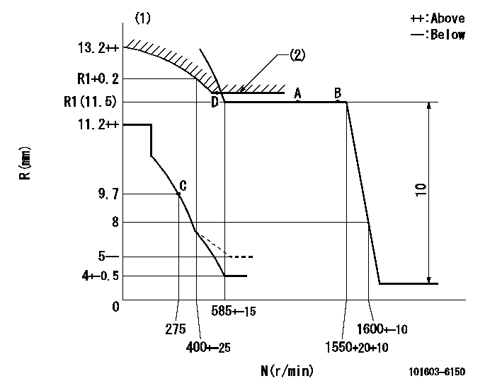
N:Pump speed
R:Rack position (mm)
(1)Damper spring setting: DL
(2)Excess fuel setting for starting: SXL
----------
DL=6.5-0.2mm SXL=R1+0.2mm
----------
----------
DL=6.5-0.2mm SXL=R1+0.2mm
----------
Speed control lever angle

F:Full speed
----------
----------
a=13deg+-5deg
----------
----------
a=13deg+-5deg
0000000901
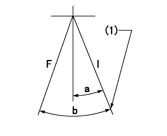
F:Full load
I:Idle
(1)Stopper bolt setting
----------
----------
a=9.5deg+-5deg b=27.5deg+-3deg
----------
----------
a=9.5deg+-5deg b=27.5deg+-3deg
Stop lever angle
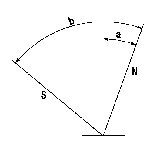
N:Pump normal
S:Stop the pump.
----------
----------
a=20deg+-5deg b=71deg+-5deg
----------
----------
a=20deg+-5deg b=71deg+-5deg
Timing setting

(1)Pump vertical direction
(2)Position of timer's tooth at No 1 cylinder's beginning of injection
(3)B.T.D.C.: aa
(4)-
----------
aa=16deg
----------
a=(2deg)
----------
aa=16deg
----------
a=(2deg)
Information:
API Degrees - Temperature Correction Chart for Diesel Fuel
Record the corrected API gravity from this chart.Table of Horsepower Correction Factors
Table 2
Corrected API
Gravity at 60° F Precombustion
Chamber Engines Direct Injection Engines (Use the correct full load RPM)
1800 2000 2200 2400 2600 2800 3000 3200
32.0
32.5
33.0
33.5
34.0 .984
.987
.990
.992
.995 .986
.988
.990
.992
.995 .986
.988
.990
.992
.995 .986
.988
.990
.992
.995 .986
.988
.990
.992
.995 .986
.988
.990
.992
.995 .986
.988
.990
.992
.995 .986
.988
.990
.992
.995 .986
.988
.990
.992
.995
34.5
35.0
35.5
36.0
36.5 .997
1.000
1.003
1.005
1.008 .998
1.000
1.003
1.007
1.013 .998
1.000
1.003
1.007
1.010 .998
1.000
1.004
1.007
1.011 .998
1.000
1.004
1.007
1.011 .998
1.000
1.004
1.007
1.011 .998
1.000
1.004
1.008
1.012 .998
1.000
1.004
1.008
1.012 .998
1.000
1.004
1.008
1.012
37.0
37.5
38.0
38.5
39.0 1.011
1.014
1.017
1.020
1.023 1.014
1.018
1.022
1.025
1.029 1.014
1.018
1.022
1.026
1.030 1.014
1.018
1.022
1.026
1.030 1.015
1.019
1.022
1.026
1.030 1.015
1.019
1.023
1.027
1.031 1.016
1.020
1.024
1.028
1.032 1.016
1.020
1.024
1.028
1.033 1.016
1.021
1.025
1.029
1.034
39.5
40.0
40.5
41.0
41.5 1.027
1.030
1.034
1.038
1.043 1.034
1.038
1.043
1.048
1.053 1.034
1.038
1.043
1.048
1.054 1.034
1.039
1.044
1.049
1.055 1.035
1.040
1.045
1.050
1.056 1.036
1.040
1.045
1.051
1.056 1.036
1.041
1.046
1.051
1.057 1.037
1.042
1.047
1.053
1.059 1.039
1.045
1.047
1.057
1.064
42.0
42.5
43.0
43.5
44.0 1.047
1.053
1.060
1.067
1.076 1.059
1.066
1.073
1.082
1.095 1.060
1.067
1.074
1.084
1.096 1.061
1.068
1.076
1.085
1.098 1.062
1.069
1.077
1.086
1.099 1.063
1.070
1.078
1.087
1.100 1.064
1.071
1.079
1.088
1.102 1.066
1.072
1.081
1.091
1.105 1.072
1.080
1.089
1.099
1.115 Use the above chart to find the horsepower correction factor.Calculating the Corrected Horsepower
Determine the rated full load horsepower from the Rack Setting Information Book.
Divide the rated horsepower by the horsepower correction factor for fuel density; the result is the corrected horsepower.Example:1674 - Truck Engine Serial No. 94B2551Rated Horsepower: 270 HorsepowerCalculations:
Table 3
1. Measured API gravity: 40.4' API at 50' (round to 40' API)
2. Corrected API gravity (see chart): 41' API at 60'F
3. Hpr correction factor (see chart): 1.038
4. Corrected Hp = Rated Hpr = 270 = 260 Hp
Correction Factor 1.038 (or 3.75% hp loss) Correcting for Fuel Density When Testing Engines on a Dynamometer
When engines are tested on a dynamometer which measures actual flywheel or drive train output, the observed horsepower is dependent on the fuel used. If the fuel being used is not 35° API at 60°F, then any dynamometer readings must be corrected to determine the output if 35° API fuel had been used. The same horsepower correction factor is used, but the formula is different:Corrected Horsepower = Observed Horsepower x Horsepower Correction FactorExample:1674 Truck Engine, Serial No. 9482551Rated (full load Horsepower: 270 Horsepower)Observed (dynamometer) Horsepower: 260 HorsepowerCalculations:
Measured API gravity: 39.6° API at 50°F (round to 40° API)
Corrected API Gravity (see chart): 41° API at 60°F
Horsepower Correction Factor (see chart): 1.038
Corrected Horsepower = Observed Horsepower x Horsepower Correction Factor 260 horsepower x 1.038 = 270 horsepower(Although the dynamometer indicated low horsepower, if the proper fuel had been used, the engine would be operating at rated output. The factory tolerance on rated engine output is 3%.)REFERENCE: For more information on dynamometer testing diesel engines, see Special Instruction Form GEG01024 .Diesel Fuel API Gravity to IbsJU.S. gallon or kg/liter Conversion Chart
The following chart may be used to convert the fuel API gravity to Ibs./U.S. gallon or kg/liter. These weights are for reference and are to be used when evaluating engine performance. Measurement of fuel flow rates can be converted
Have questions with 101603-6150?
Group cross 101603-6150 ZEXEL
Mitsubishi
101603-6150
9 400 615 113
ME032909
INJECTION-PUMP ASSEMBLY
6D15
6D15