Information injection-pump assembly
ZEXEL
101603-6060
1016036060

Rating:
Cross reference number
ZEXEL
101603-6060
1016036060
Zexel num
Bosch num
Firm num
Name
Calibration Data:
Adjustment conditions
Test oil
1404 Test oil ISO4113 or {SAEJ967d}
1404 Test oil ISO4113 or {SAEJ967d}
Test oil temperature
degC
40
40
45
Nozzle and nozzle holder
105780-8140
Bosch type code
EF8511/9A
Nozzle
105780-0000
Bosch type code
DN12SD12T
Nozzle holder
105780-2080
Bosch type code
EF8511/9
Opening pressure
MPa
17.2
Opening pressure
kgf/cm2
175
Injection pipe
Outer diameter - inner diameter - length (mm) mm 6-2-600
Outer diameter - inner diameter - length (mm) mm 6-2-600
Overflow valve
131424-5520
Overflow valve opening pressure
kPa
255
221
289
Overflow valve opening pressure
kgf/cm2
2.6
2.25
2.95
Tester oil delivery pressure
kPa
157
157
157
Tester oil delivery pressure
kgf/cm2
1.6
1.6
1.6
Direction of rotation (viewed from drive side)
Left L
Left L
Injection timing adjustment
Direction of rotation (viewed from drive side)
Left L
Left L
Injection order
1-5-3-6-
2-4
Pre-stroke
mm
3.6
3.55
3.65
Beginning of injection position
Governor side NO.1
Governor side NO.1
Difference between angles 1
Cal 1-5 deg. 60 59.5 60.5
Cal 1-5 deg. 60 59.5 60.5
Difference between angles 2
Cal 1-3 deg. 120 119.5 120.5
Cal 1-3 deg. 120 119.5 120.5
Difference between angles 3
Cal 1-6 deg. 180 179.5 180.5
Cal 1-6 deg. 180 179.5 180.5
Difference between angles 4
Cyl.1-2 deg. 240 239.5 240.5
Cyl.1-2 deg. 240 239.5 240.5
Difference between angles 5
Cal 1-4 deg. 300 299.5 300.5
Cal 1-4 deg. 300 299.5 300.5
Injection quantity adjustment
Adjusting point
-
Rack position
11
Pump speed
r/min
850
850
850
Each cylinder's injection qty
mm3/st.
60
58.1
61.9
Basic
*
Fixing the rack
*
Standard for adjustment of the maximum variation between cylinders
*
Injection quantity adjustment_02
Adjusting point
-
Rack position
10+-0.5
Pump speed
r/min
275
275
275
Each cylinder's injection qty
mm3/st.
10
8.9
11.1
Fixing the rack
*
Standard for adjustment of the maximum variation between cylinders
*
Remarks
Adjust only variation between cylinders; adjust governor according to governor specifications.
Adjust only variation between cylinders; adjust governor according to governor specifications.
Injection quantity adjustment_03
Adjusting point
A
Rack position
R1(11)
Pump speed
r/min
850
850
850
Average injection quantity
mm3/st.
60
59
61
Basic
*
Fixing the lever
*
Injection quantity adjustment_04
Adjusting point
B
Rack position
R1+0.6
Pump speed
r/min
1450
1450
1450
Average injection quantity
mm3/st.
80.5
78.5
82.5
Fixing the lever
*
Injection quantity adjustment_05
Adjusting point
C
Rack position
R1-0.4
Pump speed
r/min
600
600
600
Average injection quantity
mm3/st.
42.5
40.5
44.5
Fixing the lever
*
Injection quantity adjustment_06
Adjusting point
I
Rack position
-
Pump speed
r/min
100
100
100
Average injection quantity
mm3/st.
80
75
85
Fixing the lever
*
Rack limit
*
Timer adjustment
Pump speed
r/min
1250--
Advance angle
deg.
0
0
0
Remarks
Start
Start
Timer adjustment_02
Pump speed
r/min
1200
Advance angle
deg.
0.5
Timer adjustment_03
Pump speed
r/min
1350
Advance angle
deg.
2.4
1.9
2.9
Timer adjustment_04
Pump speed
r/min
1500
Advance angle
deg.
5
4.5
5.5
Remarks
Finish
Finish
Test data Ex:
Governor adjustment
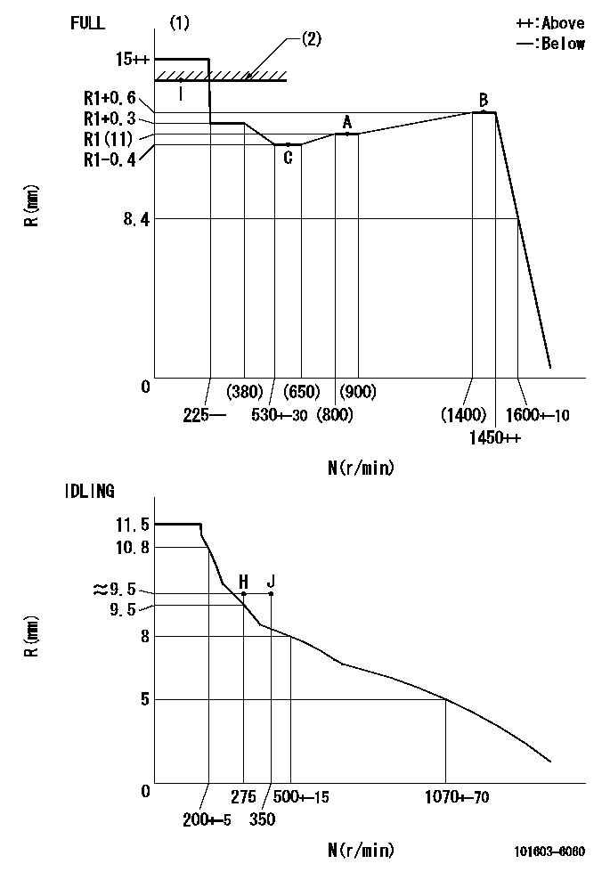
N:Pump speed
R:Rack position (mm)
(1)Torque cam stamping: T1
(2)RACK LIMIT
----------
T1=A23
----------
----------
T1=A23
----------
Speed control lever angle
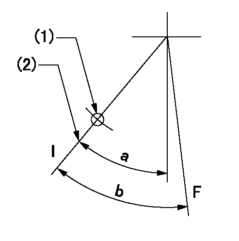
F:Full speed
I:Idle
(1)Use the hole at R = aa
(2)Stopper bolt set position 'H'
----------
aa=35mm
----------
a=33deg+-5deg b=35deg+-5deg
----------
aa=35mm
----------
a=33deg+-5deg b=35deg+-5deg
Stop lever angle
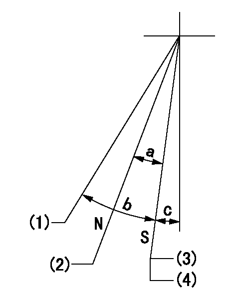
N:Pump normal
S:Stop the pump.
(1)Free (at shipping)
(2)Rack position = approximately aa.
(3)Set the stopper bolt at speed = rated point and rack position = bb. Confirm non-injection.
(4)After setting the stopper bolt, confirm non-injection at speed = cc.
----------
aa=17.4mm bb=(7)mm cc=275r/min
----------
a=17deg+-5deg b=(27deg) c=2deg+-5deg
----------
aa=17.4mm bb=(7)mm cc=275r/min
----------
a=17deg+-5deg b=(27deg) c=2deg+-5deg
0000001501 MICRO SWITCH
Adjustment of the micro-switch
Adjust the bolt to obtain the following lever position when the micro-switch is ON.
(1)Speed N1
(2)Rack position Ra
----------
N1=400+-5r/min Ra=9.2mm
----------
----------
N1=400+-5r/min Ra=9.2mm
----------
Timing setting

(1)Pump vertical direction
(2)Position of timer's tooth at No 1 cylinder's beginning of injection
(3)B.T.D.C.: aa
(4)-
----------
aa=12deg
----------
a=(1deg)
----------
aa=12deg
----------
a=(1deg)
Information:
Introduction
Do not perform any procedure in this Special Instruction until you have read the information and you understand the information.There have been isolated occurrences of excessive fuel leakage past the electronic unit injectors on some engines.Accelerated wear on the delivery valve results in an increased leak rate. The high pressure pump cannot generate enough fuel flow or volume to compensate for the leakoff rates above the critical value 38 mL (1.3 oz) per 30 seconds of cranking for six cylinder engines at a speed of 150 rpm. The high pressure pump cannot generate enough fuel flow or volume to compensate for the leakoff rates above the critical value 25 mL (0.85 oz) per 30 seconds of cranking for four cylinder engines at a speed of 150 rpm.If the engine turns over but the engine does not start, refer to Troubleshooting, "Engine Cranks but Will Not Start".Test Procedure
Before begining any work on the fuel system, refer to Operation and Maintenance Manual, "General Hazard Information and High Pressure Fuel Lines" for safety information.Refer to Systems Operation, Testing and Adjusting, "Cleanliness of Fuel System Components" for detailed information on the standards of cleanliness that must be observed during ALL work on the fuel system.
Table 1
Required Tools
Tool Part Number Part Description Qty
A 334-3221 Fuel Leakoff Kit 1
Ensure that the engine is shut down.
Illustration 1 g02103090
Injector harness
Disconnect the injector harness (1) from the front of the engine.
Illustration 2 g02103093
Typical exampleNote: Direct any leaking fuel into a suitable container.
Remove the bolt (2) from the "fuel relief block" and save the bolt for reinstallation.
Illustration 3 g02103095
Fuel leakoff kit (A) Tooling (3) Clear plastic hose
Install tooling (A) to the "fuel relief block".
Slide the tooling through the banjo bolt in order to replace the bolt that was removed in the previous step.
Thread the tooling into the "fuel relief block" and slightly tighten the tooling.
Connect a plastic hose (3) onto the tooling. Place the opposite end of the plastic hose into a suitable container that is clean.
Crank the engine with the starting motor for 30 seconds.
Record the amount of fuel that has been collected. Conduct the test three times. Calculate the average of the three values.
For six cylinder engines, if more than 38 mL (1.3 oz) of fuel has been collected during the 30 second crank test, then there is high leakoff of the electronic unit injectors. For four cylinder engines, if more than 25 mL (0.85 oz) of fuel has been collected during the 30 second crank test, then there is high leakoff of the electronic unit injectors. If this is the case, replace the electronic unit injectors and the fuel injection lines. Return the original electronic unit injectors and the fuel injection lines to the parts return center.
For six cylinder