Information injection-pump assembly
ZEXEL
101603-6051
1016036051

Rating:
Cross reference number
ZEXEL
101603-6051
1016036051
Zexel num
Bosch num
Firm num
Name
Calibration Data:
Adjustment conditions
Test oil
1404 Test oil ISO4113 or {SAEJ967d}
1404 Test oil ISO4113 or {SAEJ967d}
Test oil temperature
degC
40
40
45
Nozzle and nozzle holder
105780-8140
Bosch type code
EF8511/9A
Nozzle
105780-0000
Bosch type code
DN12SD12T
Nozzle holder
105780-2080
Bosch type code
EF8511/9
Opening pressure
MPa
17.2
Opening pressure
kgf/cm2
175
Injection pipe
Outer diameter - inner diameter - length (mm) mm 6-2-600
Outer diameter - inner diameter - length (mm) mm 6-2-600
Overflow valve
131424-5520
Overflow valve opening pressure
kPa
255
221
289
Overflow valve opening pressure
kgf/cm2
2.6
2.25
2.95
Tester oil delivery pressure
kPa
157
157
157
Tester oil delivery pressure
kgf/cm2
1.6
1.6
1.6
Direction of rotation (viewed from drive side)
Left L
Left L
Injection timing adjustment
Direction of rotation (viewed from drive side)
Left L
Left L
Injection order
1-5-3-6-
2-4
Pre-stroke
mm
3.3
3.25
3.35
Beginning of injection position
Governor side NO.1
Governor side NO.1
Difference between angles 1
Cal 1-5 deg. 60 59.5 60.5
Cal 1-5 deg. 60 59.5 60.5
Difference between angles 2
Cal 1-3 deg. 120 119.5 120.5
Cal 1-3 deg. 120 119.5 120.5
Difference between angles 3
Cal 1-6 deg. 180 179.5 180.5
Cal 1-6 deg. 180 179.5 180.5
Difference between angles 4
Cyl.1-2 deg. 240 239.5 240.5
Cyl.1-2 deg. 240 239.5 240.5
Difference between angles 5
Cal 1-4 deg. 300 299.5 300.5
Cal 1-4 deg. 300 299.5 300.5
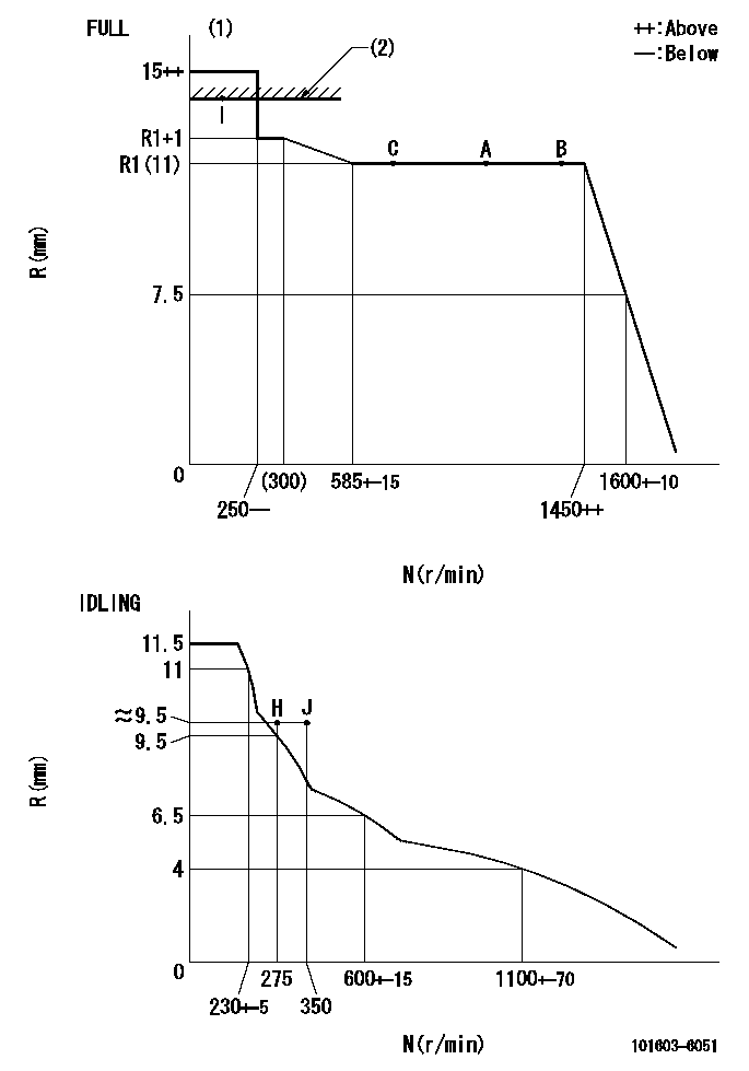
Injection quantity adjustment
Adjusting point
-
Rack position
11
Pump speed
r/min
850
850
850
Each cylinder's injection qty
mm3/st.
65
63
67
Basic
*
Fixing the rack
*
Standard for adjustment of the maximum variation between cylinders
*
Injection quantity adjustment_02
Adjusting point
H
Rack position
9.5+-0.5
Pump speed
r/min
275
275
275
Each cylinder's injection qty
mm3/st.
10.5
9
12
Fixing the rack
*
Standard for adjustment of the maximum variation between cylinders
*
Injection quantity adjustment_03
Adjusting point
A
Rack position
R1(11)
Pump speed
r/min
850
850
850
Average injection quantity
mm3/st.
65
64
66
Basic
*
Fixing the lever
*
Injection quantity adjustment_04
Adjusting point
B
Rack position
R1(11)
Pump speed
r/min
1450
1450
1450
Average injection quantity
mm3/st.
77.5
75.5
79.5
Fixing the lever
*
Injection quantity adjustment_05
Adjusting point
C
Rack position
R1(11)
Pump speed
r/min
600
600
600
Average injection quantity
mm3/st.
51.5
49.5
53.5
Fixing the lever
*
Injection quantity adjustment_06
Adjusting point
I
Rack position
14.1+-0.
5
Pump speed
r/min
100
100
100
Average injection quantity
mm3/st.
90
70
110
Fixing the lever
*
Rack limit
*
Timer adjustment
Pump speed
r/min
900--
Advance angle
deg.
0
0
0
Remarks
Start
Start
Timer adjustment_02
Pump speed
r/min
850
Advance angle
deg.
0.5
Timer adjustment_03
Pump speed
r/min
900
Advance angle
deg.
0.8
Timer adjustment_04
Pump speed
r/min
1200
Advance angle
deg.
2.6
2.1
3.1
Timer adjustment_05
Pump speed
r/min
1500
Advance angle
deg.
5.5
5
6
Remarks
Finish
Finish
Test data Ex:
Governor adjustment
N:Pump speed
R:Rack position (mm)
(1)Torque cam stamping: T1
(2)RACK LIMIT
----------
T1=A10
----------
----------
T1=A10
----------
Speed control lever angle
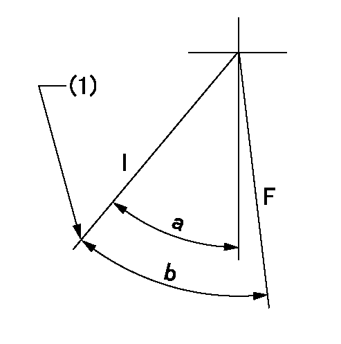
F:Full speed
I:Idle
(1)Stopper bolt set position 'H'
----------
----------
a=33deg+-5deg b=40.5deg+-3deg
----------
----------
a=33deg+-5deg b=40.5deg+-3deg
Stop lever angle
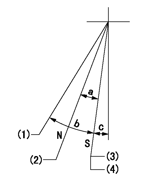
N:Pump normal
S:Stop the pump.
(1)Free (at shipping)
(2)Rack position = approximately aa.
(3)Set the stopper bolt at speed = rated point and rack position = bb. Confirm non-injection. Rack position = cc.
(4)After setting the stopper bolt, confirm non-injection at speed dd.
----------
aa=17.4mm bb=(5.4)mm cc=(7.4)mm dd=275r/min
----------
a=17deg+-5deg b=(27deg) c=2deg+-5deg
----------
aa=17.4mm bb=(5.4)mm cc=(7.4)mm dd=275r/min
----------
a=17deg+-5deg b=(27deg) c=2deg+-5deg
0000001501 MICRO SWITCH
Adjustment of the micro-switch
Adjust the bolt to obtain the following lever position when the micro-switch is ON.
(1)Speed N1
(2)Rack position Ra
----------
N1=400+-5r/min Ra=9.2mm
----------
----------
N1=400+-5r/min Ra=9.2mm
----------
Timing setting

(1)Pump vertical direction
(2)Position of timer's tooth at No 1 cylinder's beginning of injection
(3)B.T.D.C.: aa
(4)-
----------
aa=13deg
----------
a=(0deg)
----------
aa=13deg
----------
a=(0deg)
Information:
Illustration 4 g01621593
(4) The process of crimping has been improved in the location that is shown. The Fifth Improvement
The length of the bolts that secure the fuel transfer pump to the HEUI pump body have increased. The torques on the bolts that secure the transfer pump to the HEUI pump body have also increased in order to improve durability.
HEUI pumps that have been returned from the field have been inspected and broken bolts that connect the fuel transfer pump to the main HEUI pump were found.
The major symptom that is related to this issue is an oil leak between the fuel transfer pump and the HEUI pump.
The bolts that make this connection were lengthened as well as the torques were increased in order to provide a better connection.
This improvement was effective with the following part numbers: 319-0607, 319-0674, 319-0675, 319-0676, 319-0677, 319-0678, 319-0622, 319-0610 and 319-0680
Illustration 5 g01621594
(5) Location of the three bolts that have been lengthened and increased torques have been applied. Note: The applications that utilize an electric fuel transfer pump also have this improvement for the cover that goes in place of the mechanical fuel transfer pump.Note: Refer to Special Instruction , REHS3830 for the following items: parts information, installation of parts and torque procedures that are related to this improvement.All current remanufactured part numbers are being built with the latest improvements. A list of all the current new part numbers and the part numbers of the remanufactured equivalent can be seen below.
Table 1
Current New Part Numbers Remanufactured Equivalent
319-0607 -
319-0674 -
319-0675 10R7145
319-0676 10R7146
319-0677 10R7147
319-0678 10R7148
319-0622 -
319-0610 10R3044
319-0680 - Note: All part numbers that are referenced in this publication were current on 15 July 2008. Part numbers are subject to a change.
Table 2
New Part Numbers Serial Number Prefixes that Use the Part Numbers
319-0607 S/N:532, ; S/N:551, ; S/N:511, ; S/N:521, ; S/N:522, ; S/N:525, ; S/N:535, ; S/N:541, ; S/N:545, ; S/N:552, ; S/N:B3T, ; S/N:B9D, ; S/N:B9M, ; S/N:D9G
319-0674 S/N:C7D, ; S/N:C7P, ; S/N:C7Z, ; S/N:M7A
319-0675 S/N:HEP, ; S/N:BTM, ; S/N:CAP, ; S/N:CGZ, ; S/N:GAG, ; S/N:HAA, ; S/N:JAB, ; S/N:JCD, ; S/N:KDD, ; S/N:MCA, ; S/N:CYA, ; S/N:GKX, ; S/N:JNK, ; S/N:RBH, ; S/N:MKM, ; S/N:MSD, ; S/N:MSL, ; S/N:CEX, ; S/N:CEH, ; S/N:BCP, ; S/N:CLJ, ; S/N:AEM, ; S/N:AFM, ; S/N:BLE, ; S/N:BLT, ; S/N:BMK, ; S/N:BNL, ; S/N:BPM, ; S/N:BRJ, ; S/N:CAD, ; S/N:FDT, ; S/N:ACJ, ; S/N:ADE, ; S/N:BNC, ; S/N:BPP, ; S/N:BPZ, ; S/N:AAX, ; S/N:AGM, ; S/N:BMJ, ; S/N:BMY, ; S/N:BPS, ; S/N:BRZ, ; S/N:AEP, ; S/N:DAE, ; S/N:L5J, ; S/N:BRE
319-0676 S/N:101, ; S/N:102, ; S/N:103, ; S/N:104, ; S/N:125, ; S/N:202, ; S/N:301, ; S/N:302, ; S/N:AMZ, ; S/N:B1K, ; S/N:B2L, ; S/N:B3M, ; S/N:B4N, ; S/N:CAP, ; S/N:CBK, ; S/N:D3C, ; S/N:DKY
319-0677 S/N:ECH, ; S/N:AWN, ; S/N:CJX, ; S/N:JKR, ; S/N:JLS, ; S/N:JGK, ; S/N:BYE, ; S/N:T2D, ; S/N:DFP, ; S/N:SYM, ; S/N:JJG, ; S/N:LAB, ; S/N:EJC, ; S/N:KJR, ; S/N:PEH, ; S/N:CJM, ; S/N:GBR, ; S/N:KDG, ; S/N:KBE, ; S/N:DBH, ; S/N:SCR, ; S/N:GPB, ; S/N:PKE, ; S/N:C7K, ; S/N:C9M, ;