Information injection-pump assembly
ZEXEL
101603-6050
1016036050

Rating:
Cross reference number
ZEXEL
101603-6050
1016036050
Zexel num
Bosch num
Firm num
Name
Calibration Data:
Adjustment conditions
Test oil
1404 Test oil ISO4113 or {SAEJ967d}
1404 Test oil ISO4113 or {SAEJ967d}
Test oil temperature
degC
40
40
45
Nozzle and nozzle holder
105780-8140
Bosch type code
EF8511/9A
Nozzle
105780-0000
Bosch type code
DN12SD12T
Nozzle holder
105780-2080
Bosch type code
EF8511/9
Opening pressure
MPa
17.2
Opening pressure
kgf/cm2
175
Injection pipe
Outer diameter - inner diameter - length (mm) mm 6-2-600
Outer diameter - inner diameter - length (mm) mm 6-2-600
Overflow valve
131424-5520
Overflow valve opening pressure
kPa
255
221
289
Overflow valve opening pressure
kgf/cm2
2.6
2.25
2.95
Tester oil delivery pressure
kPa
157
157
157
Tester oil delivery pressure
kgf/cm2
1.6
1.6
1.6
Direction of rotation (viewed from drive side)
Left L
Left L
Injection timing adjustment
Direction of rotation (viewed from drive side)
Left L
Left L
Injection order
1-5-3-6-
2-4
Pre-stroke
mm
3.3
3.25
3.35
Beginning of injection position
Governor side NO.1
Governor side NO.1
Difference between angles 1
Cal 1-5 deg. 60 59.5 60.5
Cal 1-5 deg. 60 59.5 60.5
Difference between angles 2
Cal 1-3 deg. 120 119.5 120.5
Cal 1-3 deg. 120 119.5 120.5
Difference between angles 3
Cal 1-6 deg. 180 179.5 180.5
Cal 1-6 deg. 180 179.5 180.5
Difference between angles 4
Cyl.1-2 deg. 240 239.5 240.5
Cyl.1-2 deg. 240 239.5 240.5
Difference between angles 5
Cal 1-4 deg. 300 299.5 300.5
Cal 1-4 deg. 300 299.5 300.5
Injection quantity adjustment
Adjusting point
-
Rack position
11
Pump speed
r/min
850
850
850
Each cylinder's injection qty
mm3/st.
65
63
67
Basic
*
Fixing the rack
*
Standard for adjustment of the maximum variation between cylinders
*
Injection quantity adjustment_02
Adjusting point
H
Rack position
9.5+-0.5
Pump speed
r/min
275
275
275
Each cylinder's injection qty
mm3/st.
10.5
9
12
Fixing the rack
*
Standard for adjustment of the maximum variation between cylinders
*
Injection quantity adjustment_03
Adjusting point
A
Rack position
R1(11)
Pump speed
r/min
850
850
850
Average injection quantity
mm3/st.
65
64
66
Basic
*
Fixing the lever
*
Injection quantity adjustment_04
Adjusting point
B
Rack position
R1(11)
Pump speed
r/min
1450
1450
1450
Average injection quantity
mm3/st.
77.5
75.5
79.5
Fixing the lever
*
Injection quantity adjustment_05
Adjusting point
C
Rack position
R1(11)
Pump speed
r/min
600
600
600
Average injection quantity
mm3/st.
51.5
49.5
53.5
Fixing the lever
*
Injection quantity adjustment_06
Adjusting point
I
Rack position
14.1+-0.
5
Pump speed
r/min
100
100
100
Average injection quantity
mm3/st.
90
70
110
Fixing the lever
*
Rack limit
*
Timer adjustment
Pump speed
r/min
900--
Advance angle
deg.
0
0
0
Remarks
Start
Start
Timer adjustment_02
Pump speed
r/min
850
Advance angle
deg.
0.5
Timer adjustment_03
Pump speed
r/min
900
Advance angle
deg.
0.8
Timer adjustment_04
Pump speed
r/min
1200
Advance angle
deg.
2.6
2.1
3.1
Timer adjustment_05
Pump speed
r/min
1500
Advance angle
deg.
5.5
5
6
Remarks
Finish
Finish
Test data Ex:
Governor adjustment
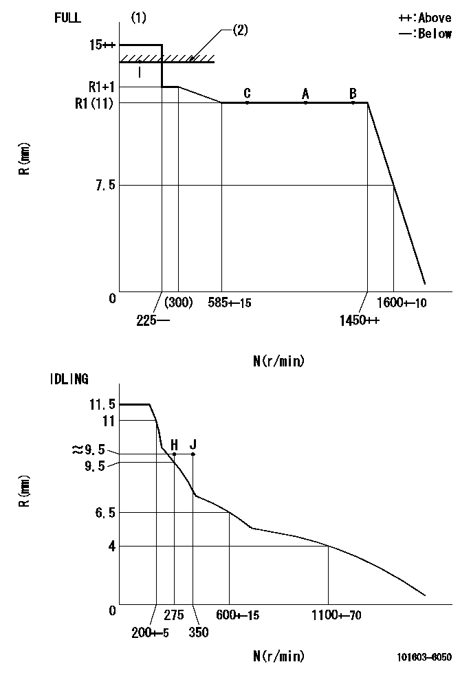
N:Pump speed
R:Rack position (mm)
(1)Torque cam stamping: T1
(2)RACK LIMIT
----------
T1=A10
----------
----------
T1=A10
----------
Speed control lever angle
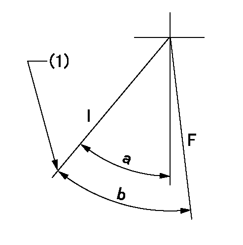
F:Full speed
I:Idle
(1)Stopper bolt set position 'H'
----------
----------
a=33deg+-5deg b=40.5deg+-3deg
----------
----------
a=33deg+-5deg b=40.5deg+-3deg
Stop lever angle
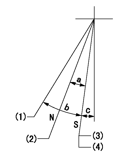
N:Pump normal
S:Stop the pump.
(1)Free (at shipping)
(2)Rack position = approximately aa.
(3)Set the stopper bolt at speed = rated point and rack position = bb. Confirm non-injection. Rack position = cc.
(4)After setting the stopper bolt, confirm non-injection at speed dd.
----------
aa=17.4mm bb=(5.4)mm cc=(7.4)mm dd=275r/min
----------
a=17deg+-5deg b=(27deg) c=2deg+-5deg
----------
aa=17.4mm bb=(5.4)mm cc=(7.4)mm dd=275r/min
----------
a=17deg+-5deg b=(27deg) c=2deg+-5deg
0000001501 MICRO SWITCH
Adjustment of the micro-switch
Adjust the bolt to obtain the following lever position when the micro-switch is ON.
(1)Speed N1
(2)Rack position Ra
----------
N1=400+-5r/min Ra=9.2mm
----------
----------
N1=400+-5r/min Ra=9.2mm
----------
Timing setting

(1)Pump vertical direction
(2)Position of timer's tooth at No 1 cylinder's beginning of injection
(3)B.T.D.C.: aa
(4)-
----------
aa=13deg
----------
a=(0deg)
----------
aa=13deg
----------
a=(0deg)
Information:
Procedure
Note: Prior to performing the analysis with the APC, be sure to read and understand all the interferences listed in the "Interferences Inherent In the Fuel Sample" section of this document. Ensure that all precautions have been taken to minimize the affect of skewed results due to improper sampling, handling, or preparation.
Obtain the fuel sample to be analyzed in an appropriate sample bottle as described in the "Fuel Sample Preparation" section. Manually or mechanically shake the sample vigorously for 30 seconds. When manually shaking a sample, ensure thorough mixing of the sample by turning the bottle so that the lid is facing downward. Shake by moving the wrist and/or forearm up and down as rapidly as is comfortable for the 30 seconds.Note: Degassing samples can be accomplished with either the use of an ultrasonic bath or with the use of a vacuum pump.
Immediately degas the sample, by partially opening the lid to the bottle and placing the sample upright in the degassing unit. Perform only one of the degassing methods. An ultrasonic bath is the best method for degassing a sample. An ultrasonic bath takes the least amount of time minimizing the impact of particle settling.Note: The purpose of partially unscrewing or opening the lid is to promote quick degassing of the sample. Air bubbles to remaining near the surface of the sample following the degassing process are acceptable.
Illustration 5 g01741117
If an ultrasonic bath is unavailable, an alternative method of degassing the sample is with the use of a 1U-5718 Oil Sampling Vacuum Pump. Ensure the 1U-5718 Oil Sampling Vacuum Pump is clean before beginning the degas process.Note: Rubber is to be placed over the hole of the tubing for the pump to develop and hold the required vacuum.
With the sample to be analyzed in the sample bottle, thread the bottle into the bottom of the 1U-5718 Oil Sampling Vacuum Group. Operate the pump to create a vacuum. Maintain the vacuum until all air bubbles have risen to the surface of the sample and dissipated.
If an ultrasonic bath or a vacuum pump is not available, the sample can degas naturally. Degas the sample by setting the sample on a flat surface and leaving the sample undisturbed. If the APC performs a flushing cycle, let the sample sit for 15 seconds. If the APC does not perform a flushing cycle, such as the 293-8413 HYDAC Contamination Monitor Group or the 383-4255 HYDAC Contamination Monitor Group, let the sample sit for 30 seconds. Proceed to the "Sample Processing" section.Sample Processing
Remove the lid from the sample bottle. Immediately begin the processing of the sample on the APC that has been prepared according to the "Fuel Sample Preparation" section.Note: If more than 45 seconds elapse after the shaking of the sample, the procedure shall be restarted with shaking of the sample in "Fuel Sample Preparation" section. Shaking the sample ensures that suspended particles do not settle to the bottom of the sample, causing inaccurate particle count results.
Obtain the particle count results